A true BMS - does it exists, should it be designed?

Hi,

I’ve been wrestling with an idea of actually building my own electric long board (not many drop decks around there and I like that sort of board flex points arrangements).

But (of course I might be blind, to not see those) it became apparent to me that most of people concentrate a lot on motor controllers and actual motors but there is very little improvement in terms of BMS.

So from my experience a BMS will be responsible for:

  • energy counting coming in and out of battery to have a full knowledge of current SOC,
  • continuous monitoring of each cell voltage
  • continuous measurement of cell temperature
  • provoding balancing durring charging
  • imposing a drive and regen current for motor controllers based on SOC, cell min / max voltage and temperature.
  • dictating charge current for charger connected to battery pack

Common practice is to blend BMS with distribution unit, distribution unit is usually responsible for:

  • measuring current coming in and out of battery pack
  • comparing current current against BMS imposed limits and if those are exceeded perform a controlled shutdown (bus isolation)

Another problem that I’ve seen is that any isolation units that exists (or distribution units) are fairly limited in max current. I was considering a build with 10S running at 200A drive and 100A regen and as far as I can tell I’m on my own.

Please correct me if unit like that does exists, and please don’t try to deteriorate this topic for no reason.

I’ve also noticed that there is fair amount of people that do complain about their range and other aspects that do indicate that they smash their battery because some cells have different impedance to others (heat spots can cause that as well). Decent 18650 will give you 5000 cycles for capacity drop of 20% if used within current / voltage / temp limits. From our tests of batteries you can kill bests cells quicker than 20 cycles (drop them more than 50% of capacity), without even touching region of thermal run away. Also there seems to be not much concern about batteries going for runaway among some users … and scary is that they chose polymers that we know that those can go with decent fireball.

Now recently I was doing a small design work that included a set on nice mosfets that can do 43 amps and provide current measurement within single package and small footprint (and verrrryyyyy low ON resistance resulting in low loss).

So my intention was to actually create a BMS that allows all mentioned functionality. Now if using a right chip, there could be additional functionality include:

  • providing it with 4 can busses it could be connected to 4 separate VESC motor and dictating current limit PER wheel.
  • reading realtime wheel speed from each vesc separately
  • dictating torque request independently to each wheel
  • implementing a speed control where a central unit is reading wheel speeds and computing whenever we are in turn or not and altering torque based on those parameters.
  • implementing a simple 4 wheel control with drive and regen torque bias, still not exceeding base battery limits.
  • if one would be veeerrrryyy advantageous, by controlling each wheel separately there is a way to implement stability program that would allow driving a softer suspension setup downhill, and having motors eliminate potential of tail oscillation.

FYI, I don’t fancy changing it into any form of business and would prefer for it to be open source so more people can benefit (I like the vesc initiative !)

3 Likes

Have you checked these BMS designs from members of this community? I am pretty sure they offer most of this features. Just to let you know they exist.

Batman BMS

DieBie BMS

2 Likes

Im definately up for more ‘‘open source’’ / customizeable bms designs out there!

Raphael Chang’s one seems to be promising… but the work developing these seems a bit slow and im not sure when we will see them more openly available to everyone… so as i said earlier, the more options we have, the better!

The idea about individually controllable wheels also sound nice… Though for start a bms which can do some ‘‘coulometer’’ functions and display energy spent/received would be nice itself

That is one of the easier functions and most of these smart bmses can do that.

DieBie is not being manufactured by a company, you have to use the open source files and print and assemble it yourself.

BatMan is in a beta production run right now.

How about combining the functionality of a soft switch, (smart)BMS and VESC on one PCB with shared heatsink?

Ideally being able to configure all functionality through one piece of software through bluetooth…

1 Like

Take a look at this BMS

http://www.chargery.com/BMS16.asp

Thanks a lot for that, I seen not only me seen the problem :slight_smile:

From my experience coulometer is the worst possible solution - When we passed our daily battery data through coulometer we got SOC drift of 35% … unfortunately more complex computation of energy flow is required (and a rough value of internal impedance of cells has to be known)

I’m not saying that they don’t do it - just bringing up that coulometers are very unreliable in real world.

So in 4x4 skatebords one would have 4 bms units ? who provides ESP then ? I see possibility of having 4x50A continous BMS units with isolation units that somehow synchronise, which will simplify design by not having to use large components for 200A, BUT then one will be hit with 4 x single bms cost + 4 x failure modes + you still need master unit … design would be messy here UNLESS you have some brilliant idea (not the first time I’ve not seen obvious and simple solutions so go for it!)

I’m not sure, but stuff that I’ve seen on this link is far from being “skateboard ready” … could you please elaborate how you see use of their stuff here ?

So far I see that 100A continuous is max so far. Mostly a single CAN buss … just to make people realise the problems with esp : good abs has separate inputs from each wheel ( analog so there is no problems with max bandwidth ) and if you’ve looking for active suspensions - most manufacturers use FlexRay - which gives 100x the bandwidth of CAN …

(and I know how some will approach it “it’s a overkill” “you’re nuts” etc … but I would rather implement eps the right way, because it’s not a car with a lot of body panels around you and a tinny error means that your face becomes a crump zone :confused: )

Thanks to everyone for their input and not taking down the thread with usual “why would you numbty” or “use search”. Cheers guys !

Less than 3% of builds on this forum are 4WD, in that case it wouldnt be practical indeed.

I dont think ESP should be applied through the BMS, but through the motor controllers. CAN-bus connected vescs can already apply traction control, so ESP is only a bit of coding away.

Design would be much less messy with integrated BMS+softswitch+VESC on a single PCB as it becomes one big plug and play device. Plug in your switch, receiver, batteries, balance leads, motor leads and sensor leads, done! Then connect through bluetooth to set all parameters in one PC app.

On dual drive builds you will have one BMS too many, though you could also make a version with dual vesc + bms +switch.

Im not going to try designing this, but i’m just sharing what I would want to buy as a perfect electronics solution.

2 Likes

Why on earth would you like 103.7200=7.4KW passing trough a BMS? You should really considder external means of current measurement (hall based) for these powers. My BMS can do up to 120A discharge but that is really maxing it.

Why would you need 4 times a CAN bus? Do you know how a CAN bus works :stuck_out_tongue:?

ESP sounds coowl but I think its to complex for esk8 application…

1 Like

@Stef only 3% ? that’s a pitty … but I guess people don’t want to spend to much on their eskate hobby. “Oh well”.

Anyway in terms of ESP, I strongly disagree with it being implemented by motor controller (at least in current shape of vesc) to do this you need to shift a lot of data on CAN (2 might be OK but 4 on same buss will be to slow). Also for esp or any decent traction control you need at least a most crude yawn sensing … even ESR does use gyro. Another thing is a processing power … current STM32 that is used on vesc is a nice bit of kit but I would not go below 300MHz for any meaningful computing - specially that vecs is pretty busy with phase control and sensing!

For a late joiner @JTAG I think you are slightly wrong with your assumptions.

First of all 3.7V is a static nominal (100% saged) voltage for kobalt cells, when heavy loaded those will drop to 3V easily - so it’s actually 6kW. If we are talking about polimer cells this voltages will go down under load even more :* climbing over a 25% will give you rather amazing power drain

Second, hall sensors are cheap and crap and nobody in automotive that cares about their name uses it :slight_smile: Using transistors of a soft switch for current measurement is not by any means perfect but it does simplify design, reduces bom, and provides a better measurement than hal effect :slight_smile: [and before you will go into proving me that some people do, most of controllers for EV that used hal is DEAD because on high noise buses it’s just not functioning properly - and nobody in motor controller business is looking and stoping using batteries as noise dump]

Third - no, I did not know how CAN works up until now, I always assumed that you can put infinite amount of nodes, with infinite bandwidth, no noise caused “tripple message cascade” problems (error -> error frame -> resend) (that is single handedly cause a rule of thumb not to create systems with bus content of more that 30%). I just design vehicles using kw2000 over VPW … you know to show that I’m “a pro”

Fourth - sorry for throwing out my toys out of pram :stuck_out_tongue: anyway point of 4 CANs was to create any meaningful esp, for simple max current propagation one CAN is more than enough

Fifth - your bms is something I would go for with RWD setup where no other means (like esp) are neaded :slight_smile:

But I see that there is more emerging problem for eskate people - a increasing complexity that leads to harder setup and has more failure points.

Anyway anybody could ask a creator of vesc this two simple questions

  • how is he coping with switching noise on his system - what if 2 (or even 4) controllers would occupy same PCB
  • what is a max cable length for 3 phase between controller and motor ?

maybe there would be a way to kill multiple birds with one stone and get everything merged into a singular design (that way heat rejection would be less of a problem, less cabling … as @Stef points out a easier setup.

Dajum, didn’t expect this for a reply. Your type of arrogance makes me feel sick, goodbye :sunglasses: .

2 Likes

Hi! Im seeing a wide list of topics adressed here in one reply @tomtom13 So im really starting to wonder from which ‘‘industry’’ are u coming and how many years of experience you are having into it :wink:

Non the less, I found 2 topics of interest from what you pointed out:

Can you describe this more precisely. How exactly transistors are used for measurement? To my understanding this means that the process you describe is what Vesc does… measurent shunt current etc… but then again, if you use sensored setup, the halls are still in the magnets… so this part is a bit unclear to me…

Why do you say that polimer cells ‘sag’ even more heavy under load?

I always though that li-ions are the ones which sag, while lipo cells maintain higher output.

Accounting for voltage drop and power decrease seems smart, im sure not everyone is accounting for this.

Sorry for offending you ( I did said sorry for throwing my toys out of pram :* ) but I guess if that is so easy for you to get offended than you will be not willing to change your desing. FYI I definitely don’t see that as a negative trait!

Hall efect sensors don’t limit to measuring magnetic field in motor / or “noticing a passing magnet”. There were at some point measuring systems (not invasive) that would measure a current by having a coil winded over a wire in which you were measuring current (like current clamp meter - just cheaper) their accuracy was god awful when used in EV because motor controller produces a lot of noise and it will always produce way off measurement.

using a trnsistor - mosfet in ON position has a fairly linear Rdson, lets say 16mOHM. When you pass current through transistor it will give you a voltage drop - you measure this voltage drop and apply a simple formula: V/R = I. So if you had a 16mV drop on your transistor with 16mOHM Rdson - than current between drain and source will be 1A.

There are transistors that have this measurment units build into them ! Case point: VN5T016AHTR-E

so why complicate ? sink sense output through resistor to ground and connect high side of resistor to ADC of you choice and you’ve got a very accurate current measurement for a penny (yes you can do it even better but for eskare down to 0.01A is enough !)

Polimers are a slightly different beast to what people think of them. Reason people use polimers are price / weight / power to energy ratio. Polimers also have a different chemistry to usual kobalt 18650, so for like to like test (discharging both chemistries with 1C) polimers will sag far less than kobalt. Now as we know reality of polimer cell is that they always quote astounding C discharge rating - 165C was highest that I’ve seen but it still means that 6000mah battery will discharge with roughly 900A within 20 seconds. Battery will survive that without significant degradation or going into thermal run away so everybody is happy, but what nobody actually measures is that cell voltage at this discharge rate can drop down to 0.5V. So yes you’ve got a brilliant current but not as much power output that you’ve expected.

So bottom line is that when reaching a genuine max C discharge rating of cell, kobalt cells because those are not rated to cosmic levels will always give higher load voltage than polimers.

If you want to get a decent source of current measurements under load for 18650: http://lygte-info.dk/review/batteries2012/Common18650Summary%20UK.html

here for example is a briliant sonny cell ( on of the best ) http://lygte-info.dk/review/batteries2012/Sony%20US18650VTC5A%202600mAh%20(Green)%20UK.html

Cell was fully loaded and taken STRAIGHT off the charger (no time to sag to nominal standby) and you can see that straight of the bat within first minute battery is at 3.3V at discharge of 30A … then it collapses down to 2.8 which bloke uses as a cut of point for kobalt cells (vise)

@Okami (just a supplementary stuff, didn’t wanted to edit previous one … it had only so many edits)

What you have to think of as well is that if you load cell:

  • with 20A (for lets say 3.7V cell) you have to provide 0.185 ohm resistance on output.
  • with 200A (for lets say 3.7V cell) you have to provide 0.0185 ohm resistance on output.

If internal resistance of the cell is arround 0.02, a 20A load does mean that internal resistance is that significant - but when internal resistance makes up a half of total loop resistance that your voltage will sag dramatically !!!

This is why I was keen on separate cell voltage measuring and adjusting a max discharge current (and letting motor controllers know) so voltages don’t drop to low. People are not aware of that but kobalt cells if depleted to low will dramatically decrease life span. Of course polimer “calendar” cells require compression so they don’t swell … so each chemistry / design has it’s downsides !

Thanks for all the great info! @tomtom13

Basically, do you refer to ‘coulometers’ as ‘devices’’ which exlusively use hall sensors?

When I pointed out to BMS with coulometer integrated, I meant more that it has current sensing integrated, has some form of a display / data output and that it replaces the need to install ‘exterior’ current sensors / power meters, for analyzing / measuring or displaying data.

Im not so sure is this super needed as there might as well be ‘ready-made’ modules for this reason but I still think it might be nice, if you could see all the energy / battery related data using bms itself.


I will get to ‘battery topic’ asap, as I saw you made a new reply and im still pondering the idea on why do you refer to ‘cobalt’ 18650 as the battery type - chemistry, which ‘handles’ load better.

it still seems to be that lipos ‘can bear’ higher load / energy output than ‘cobalt’ li-ions. For example… the same vtc 5 cell can bear a current of about 10C (2.6 ah x 10C = 26 A )

While some lipo’s can go to the ‘‘sky-limit’’ you mentioned… even over 100c per cell… it does seem logical that voltage will drop dramatically… but does it mean that in some way VTC 5 cells can output higher watts?

In reference to what are you then comparing 18650 li-ion vs lipo packs?

Typically, it seems like vtc5 can output about = ~93.6W per cell (3.6v nominal x 26A) or about 108w max (30A).

In which case… lipo pack, if outputting 25c…of let’s say 3ah capacity… will output way more…maybe the size will be bigger… so maybe you refer to the energy density per volume here …

I would assume that coulometer here is a “culomb meter” which only measures current IN / OUT of battery. Now if you look at physics of battery - if you charge it with 50A you actually put more energy into the battery than if you would discharge battery with 50A and it’s all to do with voltage sag / increase. Some folks like to think of battery as a current storage (you know a magical Ah marking) but in reality those are a chemical energy storage … so you need to measure how much energy you put IN (amps * volts) and how much you take out ( amps * volts ) and on top of that you need to account for cell internal resistance that will always convert current into heat (energy heat loss). So if you discharged 100W and charged 100 you may still end up with battery slightly less charged because you lost some energy to heat through internal cell resistance.

as I stated before we did that for fun on one BMS and we got 35% drift over a course of day of vehicle driving. It was even more funny when BMS opened contractors on our test guy in the middle of the motorway because cell voltage got to low while thinking it was 35% :))))))

@Okami Maybe you understood me wrong:

polimers handle discharge far better than cobalt. BUT they are rated to insane ratings at which they actually sag far more than cobalt cells at their max rating. So lipo at max current of 300A will sag more than 18650 at max current of 15A. Still lipo handles discharge better (due to mainly lower internal resistance). Still people strust max rating as a golden bullet for having a nominal voltage.

So which ‘amplitude’’ of battery voltage do you recommend to use?

I’ve seen this chart, I think this is somewhat smart on how to prolong battery lifetime/runtime in the long run.


Ah okay, then I can agree… yes I somehow thought you want to tell me that li-ions sag less than lipos… even if lipos are capable of way higher discharge rate.

I think if you read around, smarter people on this forum have already pinpointed out this ‘fact’ to downrate lipo batteries… and refer to C rating as maximum possible (sometimes maybe for short amount of time)

This is the ‘‘coulometer’’ to which im referring to and which would be cool, if it could be integrated into the bms circuit already:

http://www.ebay.com/itm/Battery-Capacity-Tester-Indicator-Coulometer-Lithium-Lead-Acid-8-65V-150A-BI668-/232282362560?hash=item36151b92c0:g:tw8AAOSwSlBY1ek8

http://www.ebay.com/itm/35-80V-50A-Capacity-Tester-Indicator-Coulometer-Lithium-Lead-Acid-Battery-Meter-/272018674496?hash=item3f55939340:g:~6IAAOSwYHxWH3Zg

Maybe code could be open, so that users could make their own data output displays, in a way they wish to see the info.

Basically, it has a shunt / current sensor to measure passing through current and some microprocessor drivign everything and of course measurement of voltage… then after the mcu has calculated all data, it gets output to lcd.

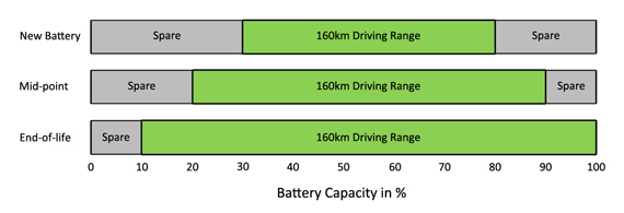
That graph is not that much wrong, Tesla was giving you 30 - 40% more capacity so after a 5 years you would still enjoy the same range.

So if you allow batteries to be drained at full “quoted by manufacturer” current (cobalts of course)

  • at 2.9V you start decreasing their life by 20%
  • at 2.8V you start decreasing their life by 30%
  • at 2.7V you start decreasing their life by 50%
  • anything below 2.7 and you are effectively asking for it.

You know, some of 18650 are rated to 80% capacity loss over 10000 cycles (f*** expensive) but when those loose capacity they will increase internal resistance -> voltage sags further -> you create more cristals in side of battery -> magic circle. so if you plan to ride you eskate only 300 times whach them down to 2.7V but be warned that battery might melt underneath you.

I’ll explain it from my perspective: I’ll got for a run on my long board -> come back -> toss it to a boot of my car. If battery is at the point of thermal runaway I will loose my car and I surely love more my beaten up old 3 series more than a long board. So i would prefer to build more expensive BUT safe eskate. That’s why safety matters to me. Personally @jtag bms looks promising but this need investigating (I seriously don’t fancy redesigning a wheel)

1 Like