Hey, did I wired my bms incorrectly? It is not charging.
Were all the cells prebalanced?
1 Like
Did you get wiring diagrams with your bms? If yes make a picture please and upload it. You use lifepo4 cells right? You charger also the right voltage for them? Did you check the output voltage?
Stupid question but we have a bit less information till now.
You sure your bms work as charge only bms? Which bms you use?
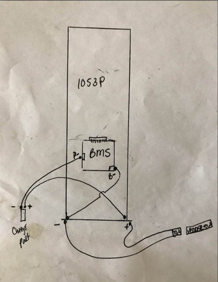
This is my already used pack, it is a 12s5p battery from 25r cells. The pack is balanced, it did kad a bms on it, I’m only changing to a smaller one. It is for charge only. I have bypass it with push to start switch. Here is the picture of the diagram.
IMO you should connect B- from your battery to the B- port on your BMS ( B- isn’t used in your picture ). Connect C- ( BMS port to charger - port ) and the + of the charging port to your B+ ( battery Terminal ).
BTW: I’m not sure about your balancing leads aswell tbh, since there is a gap between those 2 connectors. Your wiring diagram shows 13 leads. ( B- B1 B2 B3 B4 … B12 which equals 0V; 4,2V; 8,4V … ) Check the voltages on those leads and make sure everything is connected as your diagram shows ( there is another B- lead ).
The one skipped is number is B10 on this bms the B9 and B10 are soldered together, also there is a gap with no wire in the original pin for those pins. 
Okay, might be a 13s BMS which is modified to work with 12s. I have one of those aswell. If all those leads are connected correctly you still have 13 balance leads ( i count 13 in your picture, so those might be fine ).
Still, you have to make sure to connect B- port of the BMS to your battery B- port ( this connection isn’t there in your picture.
Thank you very much, I will try it, once i did plug the wider plug with out skiping the one, a short happened, it was just for a moment, do you think the bms will be okey?
Well, i can’t really tell you. Did you charge it without the B- port succesfully before? I can’t say for sure if it is possible to charge without B- port connected, if there is a B- balance lead attached. Might work, might be defective…
No, i have only soldered that one lead, I was thinking only one is needed.
So I re wired it as you said, doesn’t seem to be charging, any ideas maybe?
Why you measured minus voltage? You mixed the polarity also on the bms?
Since everything is shrinked i cant tell you if you wired it correctly. I just tried to explain you what you wiring diagram shows ( so make sure you connect the BMS the way it is shown in the diagram ).
The only difference in your wiring vs the diagram wiring is: you connect your load ( ESC ) directly to battery terminals since you want to bypass it for discharging.
So either you draw a diagram how you wired it or you have to undo the shrink wrap so we can see how you wired it.

This should be your “charging curcuit”. Make sure to connect 13 balance leads from 0V/4,2V/8,4V/…/50V
bypass on bms for direct discharge
That is exactly how I wired it, my multimeter leads are just mixed. I was measuring to see if it’s charging.
Edit: Maybe this has something to do with it?

That’s only when you use the switch. If it’s not connected it shouldn’t stop charging and discharge. I did see something in a pic you posted that could cause issues.
This shouldn’t be jumped.

I see now. It’s a 13s bms modified to do a 12s set up? Kinda funny to do that way. usually you just delete the 13th balance pin. You replaced the original bms correct. Where did you get the new one?
That’s it. It should be all single pins. No jumps. You only delete the 13 balance pin. 
This pin is jumped on the new plug, it doesn’t go anywhere. The wiring is still the same, I have only changed the plug!