power switch on my board had been acting up a bit the last couple days, where it would take like 10 seconds for it turn on after it was switched on.
then this morning i noticed power was cutting out and in, intermittently, for like 5 seconds, then it went along just fine.
so…feeling kinda sketch about my board in general, was going to open it up tonight to diagnose.
but on the way back home from work, i forget about all this, and in the last leg before getting home, there’s a slight uphill that’s really fun to bomb up, but this time during hard acceleration the power cuts out. my center of gravity is set well behind the board anticipating the acceleration, and the sudden power cut throws me off at like 25mph.
heel of my hands are burnt off, both knee caps are raw, and left elbow looks like minced meat. been downing red wine and beer to manage stinging rashes and hurt pride of falling in front of a shit load of people.
had a helmet on tho, so noggin’s fine.
not sure what the point of the story is, just wanted to share.
oh, that and i’m going back to loop keys until i can get a hold of some bullet proof anti-spark switches.
edit: it wasn’t the switch, it was bms cutting out due to voltage sag. but the issue with board powering on after like 10 seconds of being switched on still persists.
I had a very simmilar problem, it turns out the wires going to the switch itself were sub par and had problem with the vibrations degrading them. Try resoldering new wires onto the switch terminals and check if that works.
I had the problem with the original Safety Power Switch, made in Germany.
They rate the switch too high, they needed to reduce the rating by 30% and this would qualify a 10S4P as an OK current flow with enough overhead for the draw needed for long uphill runs. 14S6P is not what it can handle, but it is what it is rated for.
The solder heats up on the PCB, flows up the MOSFET terminal causing a short.
Where the problem is, I believe, is the thickness of the copper, it can’t handle the current and consequently heats up and reflows. The VEDDER PCB needs MILSTD traces or at least 2½ Oz copper, possibly a redesign to a 2 or 3 layer PCB, possibly even a laser/spot weld instead of silver or lead solder…
The use of various different passive heat sinks is recommended, but the problem still persists that the PCB is heating up past the flow temperature of the solder, and causing a short on the mosfet. The higher capacity mosfet, the need for 6 connections, vs the 2 needed for the SaftyPowerSwitch.
Same here, man. My mosfet switch started acting up too, that s**t needs to function 24/7 100%, so it was taken out and substituted with diy anisparkloop switch with regular XT90, 100ohm resistor and a rocker switch. Bulletproof. Resistor slow charges the caps and loop key powers it to the batttery voltage.
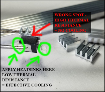
No, don’t do this. When you want to cool FETs do as follow instead :
BTW it will also help dissipate heat from the PCB.
Thank you for posting the original pic, it will save me precious time when trying to explain it. Keep them FETs cool !
@Tuomalar I know few people who got XT-90S fail on them. They upgraded to custom antisparks or relay solution. Still reliable connector but everything can happen unfortunately.
Sounds like a nasty fall. Hope your ok. You could take a spot next to @psychotiller to recover. I took a nasty spill at 25mph in San Diego and messed up my hip for two weeks. Luckily I was wearing gloves so I didn’t mess up my hands too much. My hip took all the impact.
If you are building from scratch, lap both flat 1st, it works better for thermal adhesive.
You can lap it flat with a 500-1000 grit sharpening stone, wet and dry sandpaper works well if it is on a flat surface.
FET’s are made from silica (glass), so they take this treatment well,
Not too smooth, you want the thermal adhesive to have some purchase on both surfaces.


 ur phunny…