what would be a better design when wiring up a battery pack?
A: this serpentine pattern?
B: this more linear pattern?
i remember seeing somewhere, don’t ask me for a source, that additional heat builds up where the u-turn happens in the second diagram.
i’ve been building all my packs in pattern B this whole time, considering A on the next one.
2 Likes
IMO they are the same, if you think about it on the first diagram if you rotate the first and last two columns of cells straight so you have two columns vertically it would look the same as the second diagram.
I think it just depends on where you want your positive and negative leads, second diagram you can use less cable.
1 Like
I always go B but with main leads on the outside
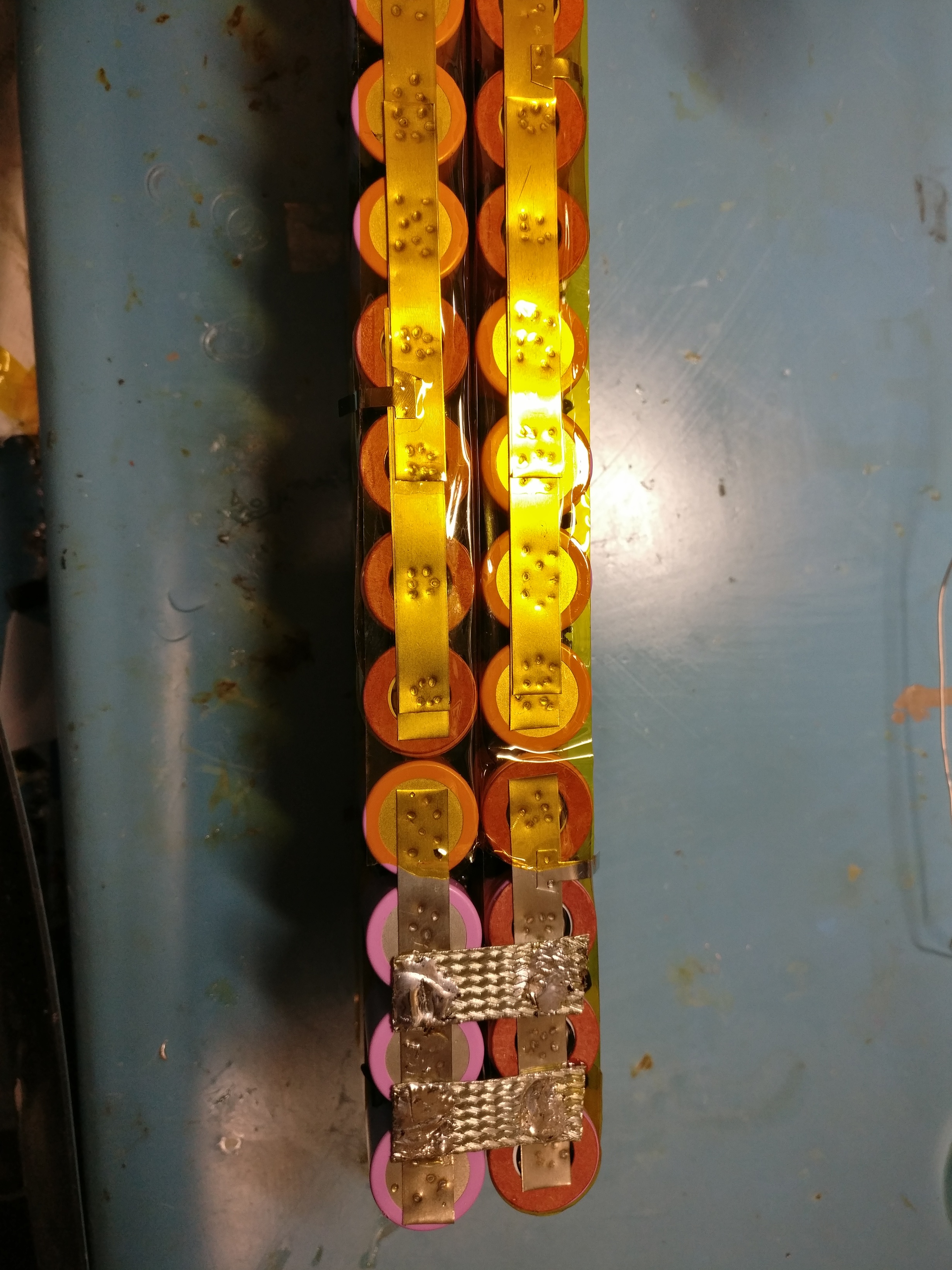
Also for the U section I use 2-3 pieces of copper braid
1 Like
B with the mains on the outside is best
A - i do it this way. Negativ is that your phase wires are on both side.
B - your chance of shorting the cells is much higher. Happened a few times here, where people don´t insulate enough between the two rows and mess up something.
Hm almost all the current is carried on serial connections. If you have a single series connection between p groups, the cells (and nickel) further from the series connections will have more resistance. This is what I believe people call uneven current sharing.
With A, you have a chance to distribute the resistance more evenly. Your diagram already has done this, as you have the series connection in the middle, not at the end, of the p group.
but, you have a chance to do even better with A, at least on the inside series connections, doing like 5 vertical lines between each p group. The outside series can be improved but not so easily.
I’m being fairly pedantic here especially for a 5p pack…
Very curious why the u-turn in B heats up.
i dont think the u turn in B would heat up any more than A. The current through the connections between each parallel group should be the same in both cases.
Only if you don’t have enough current capacity there
I always put extra material at the furthest points from the output
the single series connection in the diagram is just an illustration, I’d probably use two grounding straps in reality.
I wish I could find the video, it was a thermal camera pointed at a pack on a high current discharge test, like 10a or sumpn, and there was a temperature difference for sure.