Damn how do this happened ?
i guess water got in one of the cracks in my battery enclosure. tbh the enclosure was never planned to be permanent anyways and and i already started planning a new battery pack. now i got some motivation to actually get it finished before spring.
1 Like
Just found the time and motivation to make some progress on new enclosures.
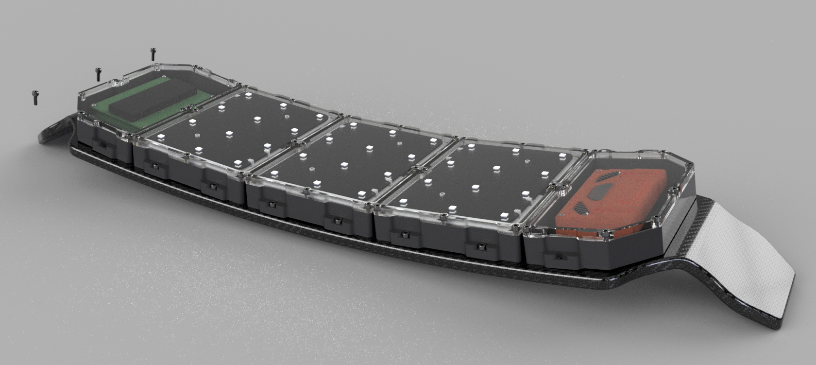
The current line of thinking is to make some custom PCB’s that will mount 2 of my 6s1p packs together to make a single 12s1p modules.

As there will be large pcb’s across the battery pack i have decided to use the opportunity and add some lights. each module currently contains 12 WS2812B addressable RGB Led’s in a 3x4 grid.
The board will have 3 of these modules in the centre with the bms at the front and Unity at the back.
Enclosures for these components will be milled from some type of plastic and have clear Poly-carbonate lids. Enclosures will be joined with thick neoprene gaskets allowing cable entrys to stay waterproof.

I have not yet finished the designs for the end enclosures but it looks promising so far.
9 Likes
Looking forward to see this. Integrated lighting is the bee’s knees.
1 Like
Small amount more progress, everything laid out better.

End enclosures still need trimming down to fit but it looks like the electronics will fit well 
1 Like
Got some more time to work on the end enclosure boxes tonight.
its starting to look quite bulky but i don’t know that there is much that i can do about that. I guess once you have 21700 cells in protective housing (24mm) and add a PCB (3mm) then put all that in a box with a reasonable wall thickness (2mm top and bottom) there is not much you can do to keep it slim.
Its going to be a big beast thats for sure.
5 Likes
BIG TORQUE requires BIG POWER.
Finally finished and sent the battery PCB’s.

PCB is 2oz copper with black silk screen. The big pads allow access to the main battery outputs whilst the smaller pads have all the battery balance points. These 12S1P modules can then be hooked in parallel to form larger battery packs on flexible boards.

I decided to remove the LED’s as they made the wiring complicated and reduced the width of current handling traces. I can always add strips on at a later date if i want to.
My current line of thinking around cabling between enclosures is to find low profile cables that can be passed directly under the seals between separate enclosures. i found some braided cable that looked good so i ordered some.

This 2mm thick by 19mm wide braid is equivalent to 5AWG cable. Its probably overkill but it looks great  IMO If its worth doing, its worth overdoing.
Also got some 22AWG ribbon cable on its way for the BMS connection points.
5 Likes
Do you have the real estate to put a smt connector on the bottom side of the pcb for the sense connections? That would require elongate the pcb a bit to clear the cell holder
I could do but im not sure it would give me much benefit. Once power is connected it will be difficult to disconnect the modules anyway plus any connection that is not soldered is a point of potential failure due to vibration.
1 Like
speaking out of experience, skinning and soldering ribbon cable is no fun at all. A connector would add a little elegance to this already badass pack

I agree, but also to get a connector with adequate current rating they end up being huge. Due to using batteries that are already packaged im super tight on space. I considered putting connectors in the middle between the packs but then the ribbon cables would have to twist and that would require extra height. additionally the cutouts either side should allow me to heat shrink the balance wires directly to the pcb providing additional strain relief.
This is how battery modules should look once assembled


13 Likes
I hope youre running at least 7 inch tires for some decent ground clearance… Im worried about this on my build as well 
I want to find something good to put on the outside of the enclosure to give it another shell of protection…
Looks really really nice otherwise!
Looks dope, i see a nice application for some flex pcb’s 
@anon64938381, This is a concern. But i dont think there is a lot i can do to reduce the height that much.
My battery packs are 24mm thick, 2mm for PCB, 2mm for braided cable, a few mm for the outer layer of poly-carbonate, a few mm for seals and foam padding. Realistically im probably looking at around 30-35mm total enclosure height
With 90mm Gummies im currently measuring around 80mm clearance under the deck at the lowest point. hopefully 45mm clearance should be enough . . . maybe . . . . . . who knows.
Might make the switch to the 6.5" urban treads but i dont know if that will actually increase the ride height at all after i flip the hangar.
3 Likes
Pcb’s turned up and they look awesome.


8 Likes
Thanks for this write up! I’m about to do a similar process with PETG! I know this was a long time ago but… BUMP!!
The reason I’ll be using PETG (vs. ABS) is that the final product is going to be a mold for vacuum infusion. Your write up was very inspiring/reassuring, and one of the only ones about petg specifically that I’ve found. Cheers for that! Excellent work dude.
I had a feeling about the rigidity from geometry, thanks for confirming that too!
1 Like
Assembled my first 12s1p pack of 21700 cells this evening to check everything fits correctly.


Now I just need to get on with milling enclosures.
10 Likes
Looks really good. Have u at any point considered selling further these battery pcbs?
I guess they could be somewhat costly and tailored to 21700 cells but non the less look really good and capable amps wise
Lots has happened so i will space this over a few posts but basically, after doing lots of cad, designing pcb’s and building a test pack i found that some of my 6S1P packs were not in the condition that i though they were in. Additionally my supply if these packs has dried up so i cant get hold of enough to finish my board using this design 
so . . .
PLAN B.
looks like i am going to have to buy cells and build my own batteries after all. Lucky for me a friend has also decided to build a diy board. This means that we will get a better price on cells and can split the cost of a spot welder making it far more reasonable to buy one.
Also, BUILDING ENCLOSURES IS HARD. making reliable waterproof enclosures is really difficult and i have earned a lot of respect for the people sell these. I have gotten to the point now where i just want to be out riding. Trying to come up with my own designs has cost me to much time and effort. at least for now im willing to spend the money and buy something that is proven and works.
After looking at a lot of cells and enclosure options it seems that there are not many enclosures avalable that fit the street carver. The easy solution would be to get a hs11 deck but im not keen on the extra length or the £200 price tag.
For 18650 cells i found the eboosted carver enclosure https://www.eboardsperu.com/product/trampa-carver/ and the kaly.nyc enclosure https://www.kaly.nyc/product-page/battery-enclosure. Both support 12s4p and fit the carver deck. I would of preferred to go 21700 however i was unable to find an enclosure that would house these and fit the carver.
I finally decided that the Kaly enclosure would be better because it is cheaper, comes will all the mounting hardware and i prefer they layout to the eboosted board. Additionally the fact that im splitting the costs with a friend means that shipping cost is halved.
Next decision was which cells to buy. After reading much information and looking at many graphs i decided on the popular Samsung 30Q https://eu.nkon.nl/rechargeable/18650-size/samsung-inr-18650-30q-3000mah.html . This decision was based on them having a good balance of capacity, discharge current and performance over life.
1 Like