BMS on 3 x 3S1P - Help me with wiring

Hi everyone, I am building my first skateboard, before of start a new topic about my configuration, I would like to ask your help to connect correctly my BMS.

I bought this model from Amazon to test on my skateboard > https://amzn.to/2IBT08F

This is the image from Amazon about the top of the BMS SL1001

This is an image about the bottom. IMG_7381

I have connected:

  • B- with the negative of the battery (black wire).
  • C- with the negative of the charger port
  • P- will go to the negative port of the VESC

I would like to connect the BMS and try to charge the batteries but I have some problems with the balance port.

My setup has: 3 batteries (5000mAh 3S1P) in series, so I have 9 cells.

Every battery has the balance port with this configuration:

  • red wire last cell
  • yellow wire middle cell
  • white wire first cell
  • black wire the ground.

Please, someone could help me to connect correctly my BMS? I am a bit confused about the balance port.

Thank you very much for you help :slight_smile: This forum is amazing and I hope to share my skateboard soon :slight_smile:

prinzipiell it´s always the same like this just that you only have 3s

hope you know that your bms can only handle 35a.

1 Like

Thank you Andy. I have 9 cells in total and the BMS support max 10 cells.

If I will connect in order the balance port for every battery to the BMS, I will have one port of the BMS empty.

How should I do? Could this involve problems?

Thank you very much :slight_smile:

I never made it by my own but I read as long as you start from first port and only last balance port is free it should work. Maybe @b264 can confirm if this is right or not. I think he knows how to wire it up right.

1 Like

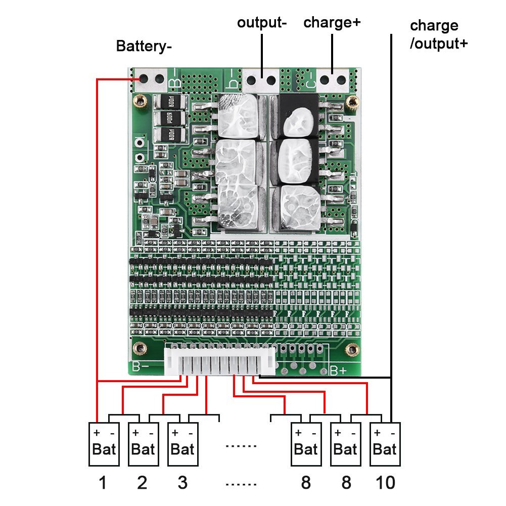
The image from amazon above is totally 100% wrong and if you use it, you will burn something down. Delete the image and never look at it again.

@00taffe Search the “Beautiful Diagrams” thread and you can post something here for verification. The most positive balance lead is the one that needs to be left unhooked.

1 Like

Thank you very much :pray:t2: I saw the thread and every schemas.

Based on the image of the bottom and on schema in the thread, i have to connect:

  • B1 to the white wire of the first battery
  • B2 to the yellow wire of the first battery
  • B3 to the red wire of the first battery and so on …
  • B9 to the red wire of the third battery

I have to left unhooked the B10 or B1? Where i have to connect B-? to the black wire of the first battery?

Hi guys, someone can help me? Thank you :slight_smile:

You should take photos of your batteries and your BMS because I’m not sure which wires are which. Also you will need a multimeter to check the voltages

1 Like

Sure, i am out from home now and i will upload all photos here asap. Thanks!

Hi, see the images below :slight_smile:

Tester

  • I put the black cable of tester to the - of the battery IMG_7695

  • Black to red wire IMG_7692

  • Black to yellow wire IMG_7693

  • Black to white wire IMG_7694

and this is the image of the BMS

Thank you for your help :blush:

B- (B0) to the black wire of the first battery B1 to the white wire of the first battery B2 to the yellow wire of the first battery B3 to the red wire of the first battery and the black wire of the second battery B4 to the white wire of the second battery B5 to the yellow wire of the second battery B6 to the red wire of the second battery and the black wire of the third battery B7 to the white wire of the third battery B8 to the yellow wire of the third battery B9 to the red wire of the third battery

NEVER solder the wires directly on the BMS. Solder them to a connector that plugs into the BMS. Only work on ONE wire at a time and finish and insulate it BEFORE you start working on another wire.

Also, a photo of the top of the BMS would help some too. Some BMS need a bridge to use it in 9S mode when it’s designed for 10S. You may have to connect B9 to B10. Not sure. Try without first.

This is the image of the top

(but the connection aren’t correct)

I tried the connections and apparently everything is working fine but in output through P- and the positive of the battery, the tension is 10v (more or less). Is this normal?

The total tension of the battery is 33.3v

I tried to charge the batteries and the tension was increased of 0.4v and every battery are at the same tension after change (11.3v)

Thank you very much for your help :heart:

I meant a photograph of your actual BMS, not a stock photo. It’s important to see if there is a bridge of some sort. That BMS PCB is desgined to be used for up to 16S but it’s configured currently for 10S. I don’t know if they put a jumper somewhere between B10 and B16 (B+) to do that, or if they did not do that. Some need it, some don’t.

​

​

​

Also, that is the image I was referring to

Please heed. You have to want to help yourself in order for someone else to be able to help :wink:

yes yes, don’t worry, the image isn’t correct and I don’t use it as a reference. See the image below of the top :slight_smile:

IMG_7707 IMG_7706

You don’t need the jumper on this BMS, just leave B10 unhooked :smiley:

Fantastic!!

So, in output from the BMS i have 10v (more or less), is this normal? I measured with P- and the positive of the battery :slight_smile:

It doesn’t sound normal, no. What is B- to B+

I have connected

  • B- to the negative of the batteries
  • P- to the out (this will go to the VESC)
  • C- to the charge connector

This is the standard configuration that I found here I have 10v between P- and the positive of the batteries.

Do you think that my BMS has any components burned?

It doesn’t sound normal, no. What is B- to B+