Build1 | TorqueBoards v2 trucks | sk3-6364-190kv | 10S5P | VESC

The core of the build plan is as follows:

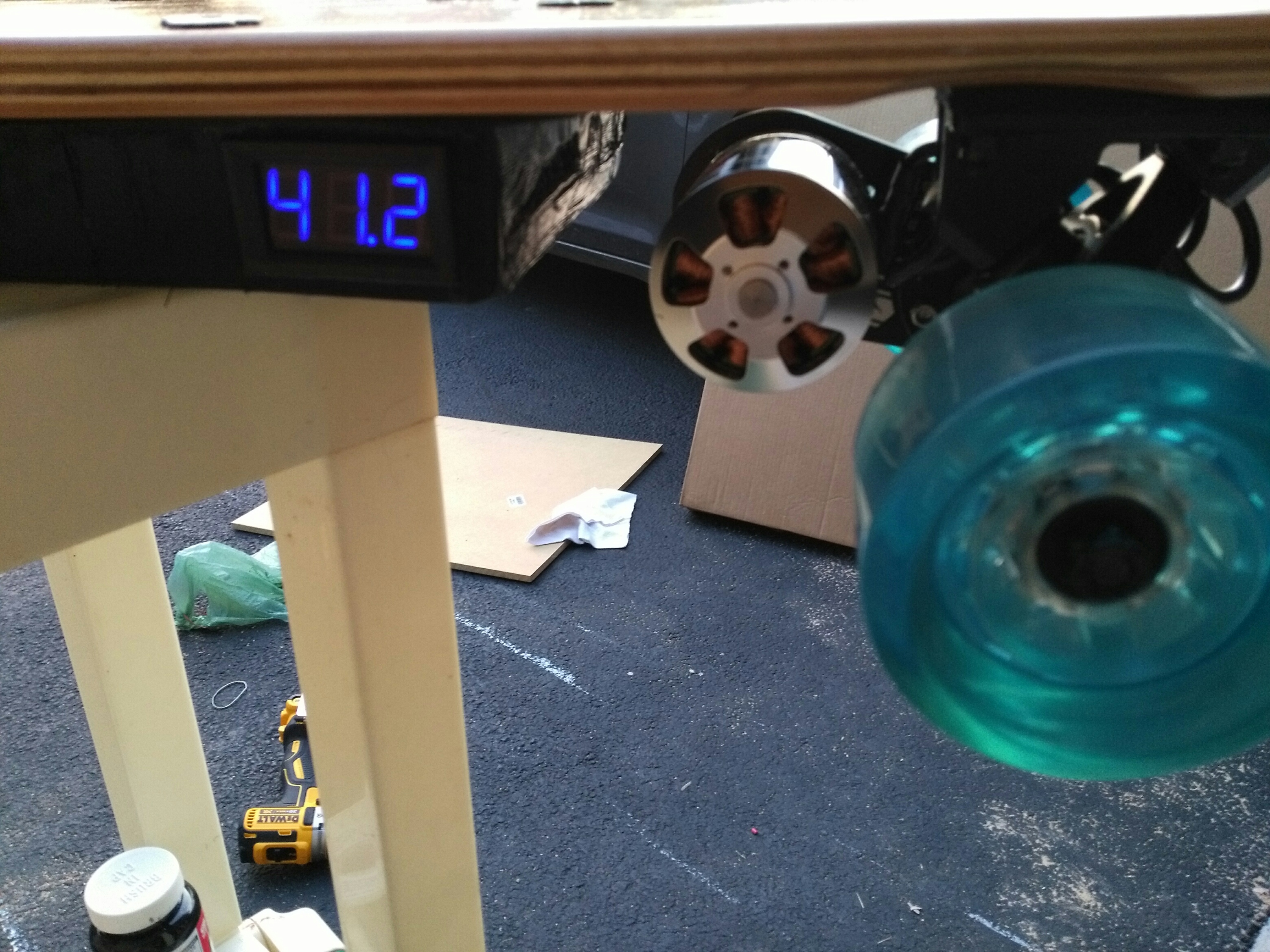
sk3-6364-190kv motor

single motor kit from DIY (trucks, 83mm wheels, 36/16 gear ratio, 12mm belt, etc.) diy-electric-skateboard-kits-parts/torqueboards-single-motor-mechanical-kit/

VESC diy-electric-skateboard-kits-parts/vesc-the-best-electric-skateboard-esc/
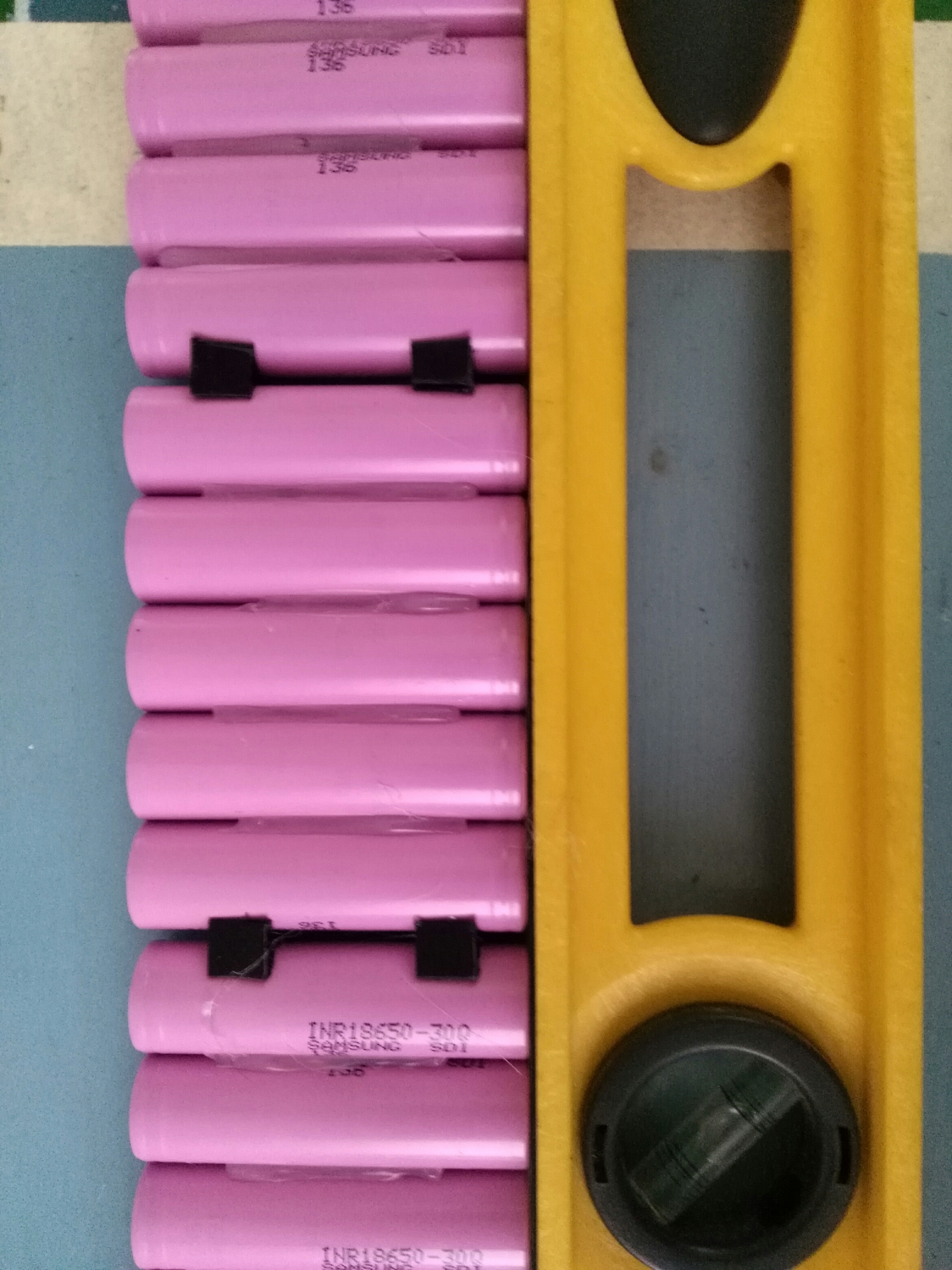
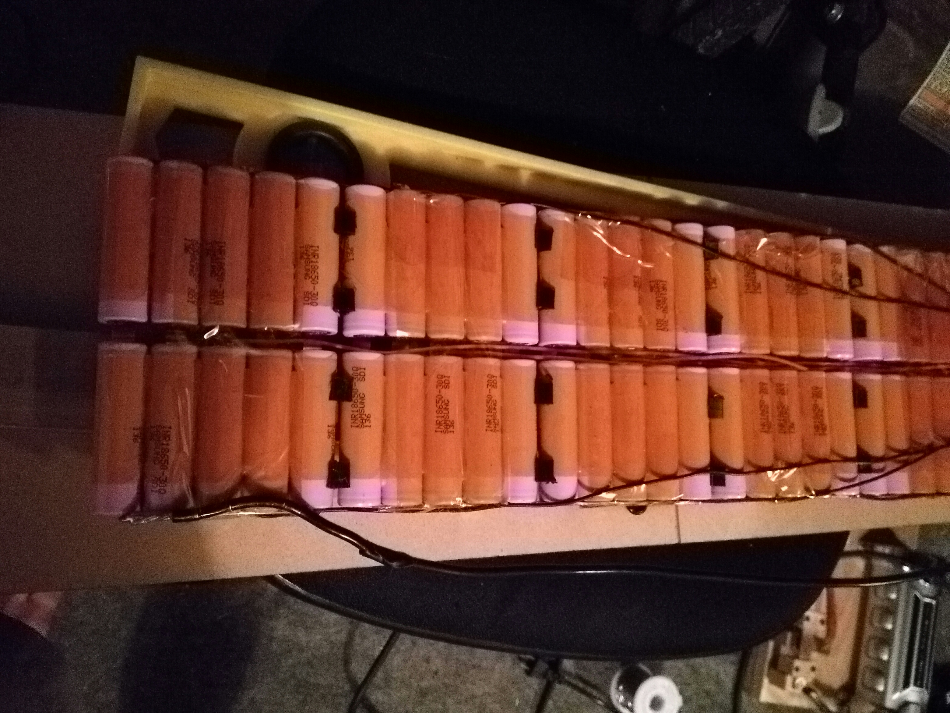
10S5P - Samsung 25r

I haven’t yet chosen a deck, remote, battery enclosure method yet but they aren’t my main priorities at the moment.

The esk8 calculator expects a top speed of 25mph/40kmh with 85% efficiency (not sure if 85 is about right or not) http://calc.esk8.it/#{“batt-type-lipo”:0,“batt-cells”:10,“motor-kv”:190,“system-efficiency”:85,“motor-pulley-teeth”:16,“wheel-pulley-teeth”:36,“wheel-size”:83}|

Honestly, that top speed is probably more than adequate. I’m more concerned about hill climbing than top speed. Do you think that this build should be sufficient to get up large/decently steep hills? Also I’ve seen recommendations to use 15mm belts with single motor builds. Should I be concerned that the belt that comes with this kit is 12mm? I’m only about 130lbs/ 59kg, so I expect that will help.

Does anyone see anything overtly wrong/ any inconsistencies with this build? Otherwise, I’m excited to take the plunge.

Thanks! -Ben

edit: I already noticed that my original build plan (213kv) slightly exceeded the recommended ERPM. I edited this post to swap to a 190kv motor 190427= 55860 - should work

You’ll be fine if you climb steeper hills every now and then but if it’s frequent dual drive is better since you have more traction, better braking, better torque.

Many people have said that the 25r cells are bad in terms of voltage sag. They recommend going with Samsung 30q cells, you will have more range and enough amperage for your build with a 10s5p of Samsung 30q cells. You can also get them from https://ru.nkon.nl for much cheaper and they ship internationally.

@Smorto Thanks for the advice and the link! I would have never guessed that the 25r cells would have worse voltage sag since the specs list them with a higher amp rating.

I’m also considering going with the sp3 149kv and moving up to a 12s5 since the presumably lower amp draw should stress the battery/motor less on hills.

Sounds good be sure to continue your build log once you start building.

I haven’t yet received my batteries/ motor, but I did build my spot welder using a 1.5F capacitor. I primarily based it on @whitepony’s design (thanks!) from here - https://endless-sphere.com/forums/viewtopic.php?f=35&t=70435&hilit=50km#p1062504

While the spring mechanism may look cool, I’m not sure that I would recommend my version of the design. I was having some pretty inconsistent test welds. I found that I was able to get the most consistent results if I kept my foot on the spring switch and completed the circuit by slowly touching the second electrode to the weld site. Whereas if I took the typical approach of first placing the electrodes before hitting the switch, the weld was typically very weak. I have my theory on why this is, but I don’t want to write anything misleading. The .3125’’ diameter copper rods that I used seem excessively thick, so I’m currently just using a couple of pieces of bus wire wire at the ends. I may try to file the rods to have thinner ends later.

1 Like

basically your cap is 75% of mine and not sure what voltage you zse for charging.

also, your switch is too far away - my switch is really close aur gap copper bars, so when my switch closes i got like 100mm^2 of copper contakt area!

4 Likes

FYI I built a similar spot welder and used it to assemble a 10s 5p battery pack. Worked very well.

Instead of the WP flat bar switch I used a starter relay off an old motorbike. The starter relay is operated by a micro switch. This gave me very consistent welds.

And it’s all finished!

Not really, but I became impatient waiting for the cells to arrive so I threw some lipos on there to give it a test run. I ended up going with the 149kv sk3, and even at the current 9S it feels pretty impressively fast to me.

Thanks @whitepony and @PB1 for the feedback! Yeah, I think the capacitor was simply too weak. I have since upgraded to a 3F cap, and I think that one will do the job. The relay idea is pretty cool! Maybe I’ll give something like that a try if I still have inconsistent results.

For the remote/receiver, I ended up choosing the Nyko Kama. However, the fact that it doesn’t have a fail safe makes me really nervous. I did the test of pulling the batteries out with full throttle, and the motor just keeps spinning. Even if you set the VESC to send a brake signal on loss of signal, since the receiver apparently keeps sending the last signal that it received to the VESC. So I may looks into a different transmitter with a proper fail safe.

I’m planning to throw on a 12S5P configuration. If they don’t all fit in a single row I may stack the last 2 of the 12 packs on top of eachother on the side opposite of the motor.

2 Likes

Cells finally arrived! Looks like I won’t be having any space limitations.

I’m having trouble finding a definitive answer. Will it be alright for me to use a 12S configuration with the @torqueboards VESC or would it be smarter to limit it to 10S to avoid frying the VESC (149kv motor)?

diy-electric-skateboard-kits-parts/vesc-the-best-electric-skateboard-esc/

1 Like

I only use 12S on my setups and I have no issue. Just stick to 190KV on 12S.

Today, I finished building the battery. With torqueboards’ assurance, I went ahead with the 12S5. This build took a lot longer than expected.

I printed these spacers to separate packs to make myself a bit more comfortable that contiguous packs wouldn’t end up shorting out.

I hot-glued the batteries for some initial stability and hot-glued the spaces to the side of one pack.

I spot-welded the inner pack first, but it looks like I forgot to take any pictures of that side.

On the outside portion, I used bus wire to carry the bulk of the current. I first soldered it the nickel strip before welding. I tried to keep it to the outer edge of the nickel strip so that I would still have enough space for the welds.

That’s not the prettiest connection for the ground wire, but I don’t think it should be a problem. You can’t realIy see what’s going on with all the solder on top, but the bus wire is bent at 180 degrees and the ground wire is wrapped around it.

Below is after adding balance wires and folding the battery. I wasn’t expecting such a large gap in the middle. Maybe it doesn’t look very large in the image.

To finish it, I used shrink wrap. However, I don’t think that I like how the pressure of the shrink wrap is making it bow in the middle. I may end up cutting it off.

4 Likes

I 3d printed a temporary enclosure in PLA. I plan to re-print in ABS once I come up with a nicer design.

I did end up cutting the shrink wrap to relieve some pressure that was bowing the batteries. I think it ended up looking cooler this way.

Routing a path for the motor wires. I kind of made a mess with the wood glue and some liquid electrical tape.

Pretty tight fit. I was getting worried the enclosure wasn’t going to be big enough.

What? Who put this there?

Yeah, I wasn’t too concerned with aesthetics since I know I’m going to be replacing this enclosure I really like this voltage indicator though. Charging swiftly at 1.6A Went with clear grip tape

I went for a couple short test rides today, and it feels great, but still definitely still needs some work. I’m having some issues keeping the motor mount tight, hopefully some more loctite will do the trick. Also, I discovered bullet connectors on the outside of the board to connect to the motors probably isn’t a great idea. I was having some cutouts that I thought were from a loss of connection with the receiver, but it turned out one of the bullet connectors was just barely hanging on. I got thrown off the board a couple times, but fortunately that was at low speed and I landed on my feet. So I suppose I’ll solder those into place.

4 Likes

Nice LHB inspired! :slight_smile: