for exapmle: there are 2 3s lipo with each 5Ah
the charger has a current of 5Ah.
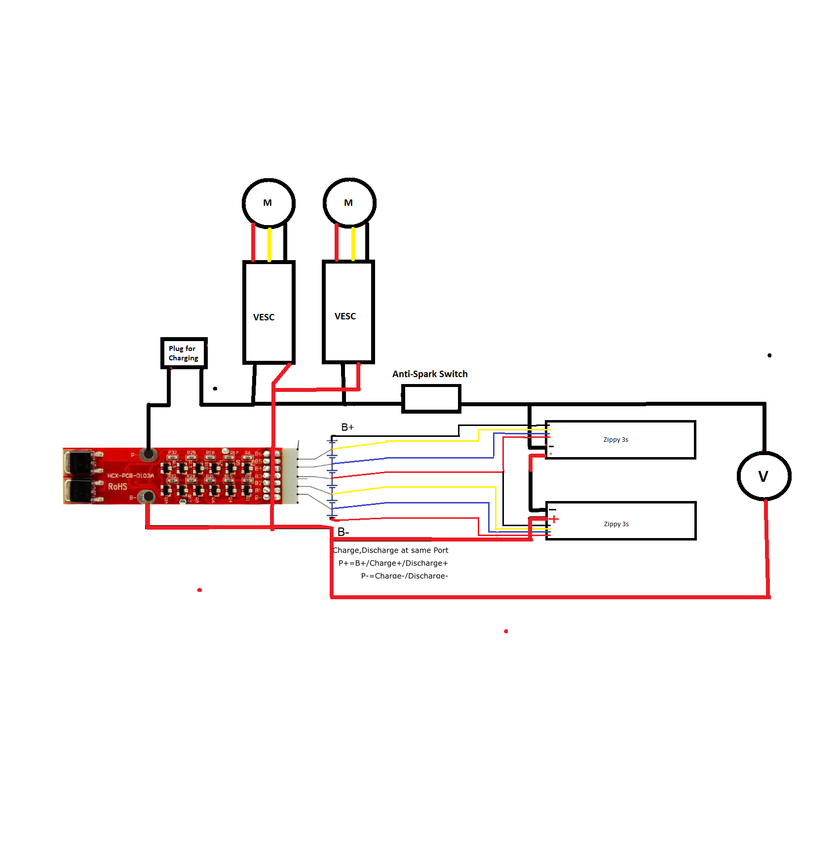
one more question: are the balance wires correct connectet to the bms?
what is with the two negative wires? should i connect them to the ground wire of the battery?
what will happen if the charger is 10 hours connect/charge
I think the battery won’t overcharge if you use the voltage of the battery, like, you have a 6s battery, so a 25.2v charger will be good! And other, if you charge when the board is off, the Bms will work fine, the overcharge still useful, but measure the voltage after the first charge
It depends honestly on the bms. No sure about that bms, but I had put 2 in parallel before like this to bypass for discharging. The problem with both was no balancing took place. I could charge it, but they never balanced. I have heard of others having more luck. I think it depends on the bms, and it’s hit or miss.
With that wiring you won’t get any overcharge protection from the bms. All you would get is passive balancing.
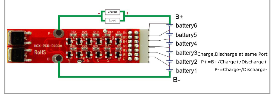
EDIT: if you look at the hobby king wiring diagram, that’s how you would get overcharge protection. You put the charger and the load between B+ and P
hey,
i misstake was to put the charger plug parrallel to the bms and battery.
i think now it is all right. is it?
so the charger plug will be in serielle between bms and battery.
The reason the letters are labled (-) on the BMS is that they’re designed to be plugged into the negative of your pack/esc. Positive wires should always go to the battery directly. Your P- should be going to your motor controller and charging negative, not the positive of your pack.
No, besides the balance leads no + wire should be going into the BMS. B- should be going to battery negative and P- should be going to VESC/charge port.
You need to have charge port go to P- and battery positive. B- should go to battery negative. You should also place the volt meter after the switch so it’s not always on.
at first i want to say. Thank you for all your help!!!
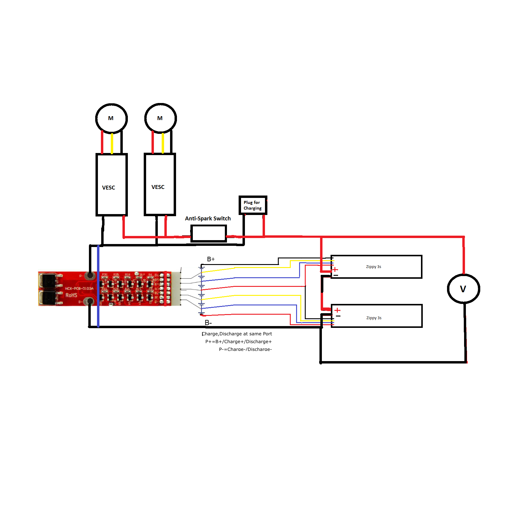
i updated the diagram again.
but now i think the bms is not bypassed. so the bms has to handel all that current. but i think i will blew up the bms, because it only can handle 10A.
hmm. but when i put the negative wire(blue wire) from vesc directly to the the battery, i dont have a overload protection. or i can install a switch ion that blue wire.
Thank you for you help and patient.
I think I will install a xt90s anti spark on that blue wire.
So for charging i just can pull out the xt90 connector.
The v is probably a voltage meter. Parallel to the batteries. Though no switch so always on. Careful
You can bypass the bus by connecting the black of the escs directly to the batteries and the red of the escs to the red on the batteries through a spark switch (xt90s) disabling discharge protection ( do be sure yours race have correct minimum voltage set) while still jabbing the charge red to the battery red and the charge black to the bms enabling overcharge protection and balancing. This is assuming this bms hag all of this protection. I don’t know t this physicist model
Whenever I said black is negative and red positive
I’m not sure but I think you have the balance wires turned around in each battery