I have an I-Wonder SK-A2. I also have a spare stock motor and spare stock ESC.
Could I, in theory, connect this spare motor and ESC to achieve a dual (diagonal) motor setup by wiring a Y-splitter to the radio receiver and battery?
I’m not that great with voltages and loads etc, but can do the soldering and wiring. Battery is rated 8.8Ah 24V.
Theoretically, most likely.
I’ve never seen one of those boards, so I’m not sure what kind of extra space there is inside, nor am i familiar enough with the setup of the speed controller to know how it’s connected to the radio, but I would imagine so. In general the second motor only makes it use a little bit more power, but each motor does less work to move the same amount and so I don’t think you’d have any issues, as long as the battery is protected enough from over current (which it should be already…)
TLDR: You’ll probably be okay in terms of how much the battery can handle, as long as it’s protected. I think space in the enclosure will be a bigger issue
Yeah, an extra motor will give you better hill climbing and torque (feels “jumpier”)
Generally a BMS will take care of the protection part. That will look like a circuit board with a bunch of wires running to inside of the battery, known as balance wires, and then you charge with a single plug in jack (without the whole balance thing to the outside).
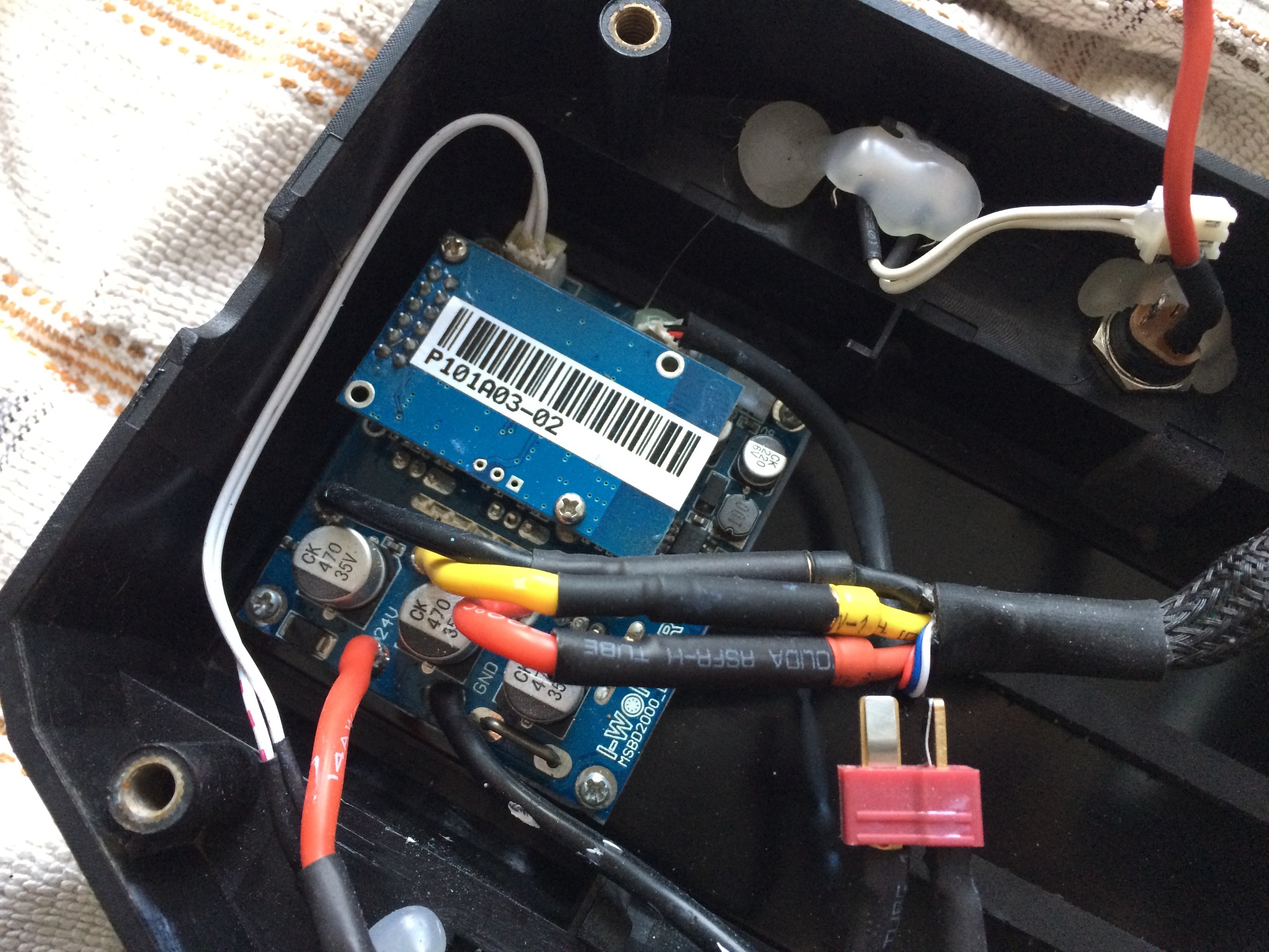
Here are some photos of the ESC. I’m not 100% sure, but is the board that’s ‘upside down’ the RF transmitter? If so, instead of trying to connect it to both ESCs, could I just leave the RF transmitter on both ESCs and have them both pair with the remote?
Anyway, I hope these photos help in determining whether my plan would work.
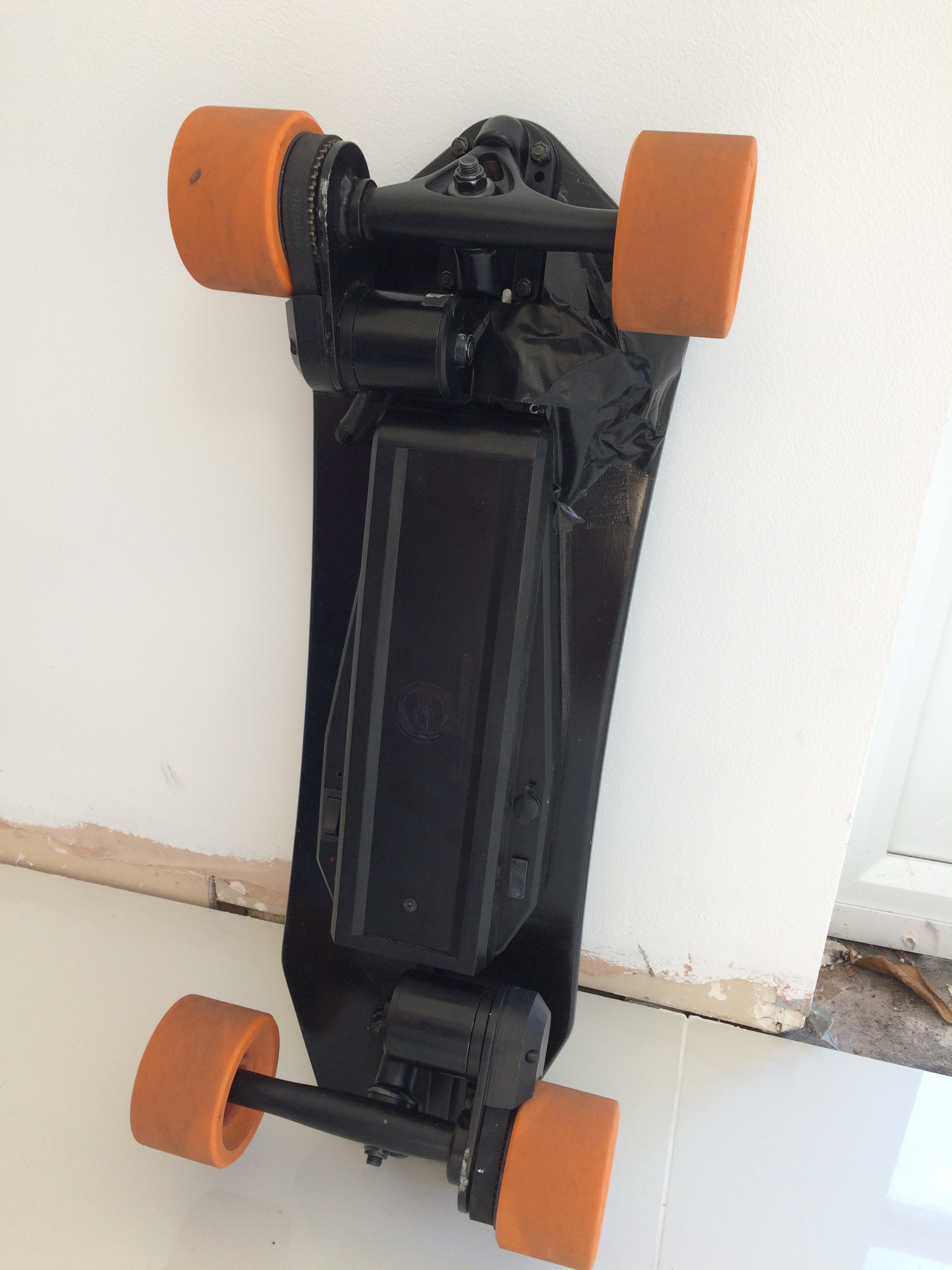
I’ve had to move the trucks and battery/ESC housing. For now, I’ve taped the 2nd ESC to the underside.
To power the 2nd ESC, I’ve taken the live and neutral from the other ESC (straightforward).
To get the motor to reverse direction, firstly i switched the red and black on the 3-phase cable. Next, i did the same on the 6-wire hall sensor cable (switched the red and black).
They now both spin in the correct direction with equal RPM (pitch is audibly the same).
Both ESCs have the stock RF receiver attached and respond at the same time.
This board now has some serious torque! Acceleration from stand still can easily throw you off!
Uphill feels so much less of a strain. The braking however, is TOO strong. Have to be really careful not to pull all the way back on the remote. The board stops DEAD. Perhaps this is something that could be overcome with VESCs in the future.
For now, ive put the board back in ‘Fun Mode’ because due to the extra torque and braking, theres a new learning curve!
Neverthless, with 2x1200W motors on a 60cm board, it feels like more than enough power than i could ever need. Very happy!