i run 12s and on fully charged batteries and with connected receiver i got over voltage error. 1 setted max voltage to 60 and problem never solved, i did connect another bms to receiver and it solved problem with over voltage error, but my motor isnt spinning. (i did set it back to 57v) and i remember that motor stopped spinning when i put 60v on max voltage. (i thought it was another problem like over voltage.)
so now i dont get any errors, but motor isnt spinning.
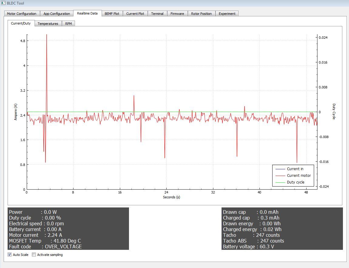
if i connect receiver to the vesc thru build-in vesc bms , then voltage varies ± 5 volts! and it shows always higher voltage.
im 100% shure that my batteries are not overcharged
screenshots with 12s batteries and reciever connected only to vesc
Wowowow - don’t do that
He supplies voltage from the UBEC to the receiver and the way he does it is the intended way. Just look at the markings on the receiver. He has the UBEC power in the right spot on the receiver. What would switching get him?
He has the SIGNAL WIRE on WRONG PLACE! On the top it says S + -, that MEANS SIGNAL, VCC and GND. And LOOK he has NO wires going to the SIGNAL pin for the RECIEVER, so he gets NO signal for the VESC, and thats why the MOTOR do not SPIN!
No he has not connected it right. He shall connect the VESC PPM output on the TOP of the Reciever where it says S + -. That thing gives him the PPM signal from the potentiometer. The Channels has nothing to do with this. They are only LOW - HIGH output for lights etc. And the power input is the VCC thing right below it.
i use external ubec because with internal i have overvoltage error. even if i set max. voltage to 60v
and in realtime tub it jumps 50v-61v like 10 times per second
“faults” in terminal says there is no faults since startup
signal wire is in right place it worked in these configuration for 5 seconds))
anyone knows where i can buy drv8302 chip? i found a place with 30 bucks shipping(
No - the receiver has a 4x3 pin matrix. the marking you mention is just the indicator that the first column is S, the second + and the third - --> this is true for all rows. The first row is just VCC, the second Ch1, third Ch2 and fourth Ch3.
The first one is used only for VCC supply and will get him NO signal. He needs to have his signal wire in the corresponding Channel row - typically channel 2 - where it is now.
you can not change the DRV yourself without a reflow oven. It has a ground pad on the bottom. If the DRV is fried it has to be sent in for repair - which is quite expensive.