Hi Community,
Here is a simple concept design for an electric longboard deck “chassis” which consists of two carbon fibre sheets bonded together either side of three carbon fibre square tubes with epoxy adhesive. The design relies on square CF tube for ease of fabrication (although you could probably use cheaper circular CF tube), with the tube providing the longitudinal strength, and the CF sheet on the bottom preventing lateral strength. The carbon fiber tube can be sourced relatively easily in up to 1 metre lengths on ebay/aliexpress/taobao, and rigid carbon fibre sheets can be made using either of these methods. While the examples used in the video are flat, there is no reason they could not be made using a concave mold. This design is flexible to accommodate dual diagonal, dual rear or 4wheel drive layouts as there is plenty of space for batteries and ESCs.
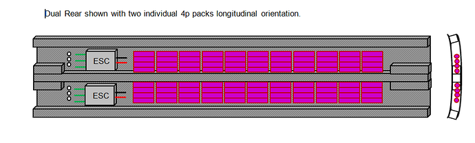
The intent here is to provide a simple, yet rigid chassis recipe to house the electronics, on which a concave deck surface and dimensions can be customised to suit. Depending on the distance between the chassis rails, it could take 18650, 20700 or 21700 size cells, and they could be oriented parallel or perpendicular to the square tube. The emphasis on this design is that the deck thickness it is no thicker than it needs to be, and is no heavier than it needs to be to maintain rigidity.
The idea is that the top surface and the bottom surface of the deck have the identical concave to the bottom, so you should only need one mold. The bottom of the deck would be carbon fibre with some unidirectional fibre embedded across the width of the deck to prevent lateral flex. Similarly the top surface (at the front and back) could incorporate unidirectional fibre as well.
The three tubes of carbon fibre square tube would provide longitudinal strength. Each component would be bonded together with the appropriate epoxy adhesive, and the resulting channels in which the batteries would be placed, would be covered with an electrical insulation to prevent shorts.
On the top surface on the deck, the area immediately in front of, and behind the lid would be made from carbon fibre, with the section in between the lid, made of fibreglass, or some other strong thin material that does not interfere with the receiver signal. The deck lid in my design would be secured with Neodymium magnets, or some other form of inconspicuous method of securing it. The receiver would be located directly under the lid to address possible EM interference from the carbon fibre.
This standard chassis design could allow a range of different deck widths and shapes, or battery configurations to be used, as unnecessary corners of the chassis can be cut out depending on the desired deck length and shape.
As most of the volume of the deck is just air, the deck would be super light and allow passive ventilation of the battery pack and ESCs at speed. If you wanted to make it water proof, you could enclose the front and back with a layer of wet layup carbon fibre, or you could also block off the ends with 3D printed plugs or grilles to let the air flow-through, or even flush mount LED headlights into the tube ends.
My design has a pair of short square CF tubes at either side of the central tube, and the ends of the deck, so that the truck baseplates and bolts have something to bolt to, although these could be replaced with wood or plastic blocks, or some other lightweight but rigid material.
The lid on top allows easy access to a swappable modular battery system, or customisable battery packs. Similarly, the design allows cells to be located in most places under the deck surface. The deck surface could be flush with the edge of the chassis, or it could be proud and create a lip, depending on the builder’s preference, or if they wanted to bolt a hidden handle onto the edge of the chassis. Any part of the chassis that sits beyond the deck’s surface can be cut away with a hacksaw, and filed flush with the deck shape.
As you can see I have not included the deck lid or a handle in my sketches.
Yes my CAD skills leave a little to be desired, but it is a concept that any keen builder who wanted a CF deck could put together.
Thoughts?
Chassis itself:

 Chassis with deck surface:
Any part of the chassis that sits proud of the deck surface would be cut away with a hacksaw, and sanded/filed flush to the deck’s shape.
Chassis with deck surface:
Any part of the chassis that sits proud of the deck surface would be cut away with a hacksaw, and sanded/filed flush to the deck’s shape.

 In the above diagram, the upper surface deck is wider than the chassis width forming a ”lip” on the deck edge. This could be done for aesthetic reasons, though the chassis itself could be widened or narrowed for multiple rows of batteries (if you wanted a super wide deck), or to hide a carry handle