hey guys,
Have any motor builders here considered using a skewed stator to reduce cogging? Or are the losses in efficiency too high? and has the maintained momentum been included in considerations about efficiency?
Cheers
hey guys,
Have any motor builders here considered using a skewed stator to reduce cogging? Or are the losses in efficiency too high? and has the maintained momentum been included in considerations about efficiency?
Cheers
As i have designed and almost build my motors i figured that skewing stator is impractical. There is no ready-made skewed stator on the market, you would need to make custom one, which costs more than most can pay. Much better solution is picking slot number/magnet count configuration that has little cogging to begin with. slot number must be dividable by 6, magnet count must be even. 4 (or 2) magnets per each 3 slots is oldest configuration, called ABC. It is also the worst. 7(or 5) magnets per each 6 slots is most common LRK/DLRK winding, most ready-made motors use it, better eficiency and less cogging but still lot of it. If you have 12 slots it is the best that can be done. With increased slot count there are new options, but as a rule best configuration will always be one in which number of magnets is greater or lower by 2 than number of slots in stator. I use 36 slots and 34 or 38 magnets for my motors. Chech this for winding schemes: http://www.bavaria-direct.co.za/scheme/calculator/ As far as my understanding goes it would be optimal to skew MAGNETS by about 0,5mm in this configuration, as optimal skew is calculated as (magnets-poles)/poles * magnet spacing, in my case (38-36)/36 * 8mm = 2/36 * 8mm = 0,44mm. This is the radial difference between both ends of the magnet. Logic behind this is that you skew magnets by an exact length that differs spacing for next magnet/slot pair - when one pair is finishing matching next one starts matching smoothly. With small diameter motors with small magnet counts even this is impractical, bencause special shaped magnets would be required - 99% of ready-made motors have no skewing. Hope i could help.
yes this helps my understanding a lot. you went a little overboard though!
was good info and
was was useful too.
Is a higher slot count always better? In operation i mean. ignoring design and construction complexity.
and yeah i did think about the skewed magnets for a little while. They would have to be like a diminished helix type shape, very tricky to engineer.
But im still wondering about the skewing.
What about this question…
if i somehow got this stator into my esk8 motor what do you think i would experience?
It would depend on the magnet configuration and spacing between magnets
Main issue is winding it, doing by hand is possible
You would experience less drag when the motor is unpowered, in a belt setup probably almost nothing since the main source of drag is the belt itself
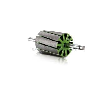
On photo you have rotor from cordless drill, designed for 20-slot commutator and zigzag winding. It has 10 slots and it is impossible to wind it for 3-phase motor. Supplier for this is JYStatorrotor chinese company.
It can be wound as 2-phase stepper motor, with nightmare cogging. It is skewed so much that you would have to skew magnets in same direction to reduce overall skew.
However you can get straight 12-slot rotor from big drill or electric hammer and it should work fine. Only downside is that drill rotor has very little space inside for the axle - machining would get tricky. Look for rotor that has as little balancing V-groove cuts on it as possible, as those mess up magnetic circuit. You can get burnt one (you need to rewind anyway) for free at power tool service point, which i did.
As for higher pole count what it does is:
This is about all for now.
Close the gaps. Its a magnet. 
Did you contact JY for a quote? how absurd was the price? it appear that the quality is really good
If you want to buy from them something they already make for someone else then it is not so bad, usually $20-$50 a piece at 20 pieces MOQ, but if you want to order custom they have to make tools for that and $5K is the price.
Here is their list of ready-made products: http://www.jystatorrotor.com/detail.asp?id=554&page=2
In this case nothing ready-made fits. Skewed stator will always be custom, better stick to skewing magnets, especially when as little as 0,5mm is best value.
Just tried to do that.
Ended up with a motor that makes 20Nm torque instead of 60! Magnetic flux was going directly from one magnet to another, without entering the stator. Magnet spacing should be 3x airgap.
Skewering magnets sounds hard as they won’t mate well to the curved rotor inside and not uniform airgap thickness
From my looking adding many poles and teeth to a motor will allow the slightest torque increase for a given diameter but that’s if the stator were redesigned to be wider and moving the airgap diameter a hair wider and making the magnets thinner. Making magnets thinner is cheaper
Less cogging is noticeable at slow speed but formally cogging is a ratcheting and has no net gain or loss. It pulls and pushes. But with many poles or skewering and less cogging it is not less resistance to spinning which is due to eddy currents and hysteresis. So I read but I still have trouble believing cogging has no net gain or loss
The stator stays put and the rotor rotates. It’s a stator above.
I saw that, but they also do prototypes using EDM, that what I’m interested, will hit them up when I finish the design
This is the best summary I’ve found so far about how everything comes together, from the book Brushless permanent magnet design by Duane Hanselman
Based on (9.11), increasing the air gap flux density is the most straightforward way to maximize the motor constant. While motor constant appears to be directly proportional to Bg, increasing the air gap flux density increases the tooth body width and stator yoke width, which decreases the slot cross-sectional area (9.12) in (9.11). As a result, motor constant increases nearly linearly with air gap flux density. This strong relationship between air gap flux density and motor constant exists because increasing the air gap flux density contributes directly to the torque in the numerator of (9.11) but contributes only weakly to increased resistance in the denominator. The influence of rotor outside radius Rro on motor constant depends on whether the stator outside radius Rso is fixed or variable. If Rso increases as Rro increases, motor constant increases linearly with outside rotor radius. Under the assumption that Rso is fixed, increasing Rro does not have a strong influence on motor constant because increasing Rro decreases the slot cross-sectional area (9.12) in (9.11) as well. Increasing the rotor outside radius diminishes A, directly through the Rro terms in (9.12) and less significantly through wtb and wsy, which increase linearly with Rw. Although the influence of Rr„ on motor constant is not strong, it remains important. Practical experience has shown that the optimum Rr0 is typically between 40 and 65% of Rso. This issue of maximizing motor constant by optimizing the ratio Rr0/Rs0 can be visualized by considering Fig. 9-2. Both motor cross sections in the figure describe four pole, twelve slot motors that have the same outside stator radius. Fig. 9-2a is a copper motor where there is greater room for windings and less magnet material. On the other hand, Fig. 9-2b is a magnet motor, having a larger outside rotor radius. In this case, there is less room for windings but significantly more magnet material. Inspection of (9.11) also shows that motor constant is related to the number of magnet poles. In addition to the square root relationship shown in (9.11), increasing the number of magnet poles also increases the slot cross-sectional area to a lesser extent because the stator yoke width decreases linearly with increasing N,„. As a result, with respect to magnet pole count, motor constant increases at a rate slightly faster than a square root rate. Motor constant as given by (9.11) ignores the winding end turns. Since the end turns create ohmic losses but do not produce torque, they directly diminish motor constant. This fact suggests that motor constant increases at a slightly greater rate with respect to Nm than that described in the preceding paragraph. This occurs because the length of the end turns are inversely proportional to the number of magnet poles since the angular coil pitch is 2/r/iV„.radM. The presence of end turns also suggests that motor constant decreases somewhat with increasing outside rotor radius. This occurs because end turn length is directly proportional to the distance between slots, which increases somewhat with respect to Rr0 if Rso is fixed. In summary, increasing the air gap flux density is the most significant way to increase motor constant. When the outside stator radius is fixed, the outside rotor radius plays an important but much less significant role in maximizing motor constant. Increasing the number of magnet poles plays a more significant role than the outside rotor radius but a less significant role than increasing the air gap flux density.
What the hell does that mean. What motor constant. Km? Hell of a long convoluted rabble.
Yeah, Km, I didn’t post everything that comes before or it would be too long
Chapter 9
Pity i didnt find that book before i started designing my motors. Most important things are correct - maximum pole count and airgap flux possible to increase motor constant. Then adjust airgap to maintain stator flux just before core saturation begins. Since i used ready-made stator only stator thickness was of my choosing, rest was derived from tiger motors. Stronger and thicker magnets were added and different magnet count used, making my creation as powerful as it is.