Yes, will be done in the next post “Stator and Axle”.
that hub looks pretty smooth. do you have any issues with urethane slippage?
Have a look at post 12:
Thanks man, continue your topic, I’m anxious!
Thanks, but converting you’ll have a 75kv motor, right? Could someone just buy the 60kv 6374 from alien?
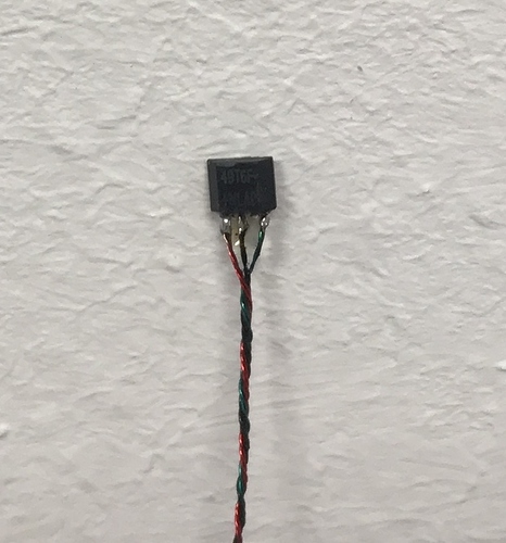
Right - maybe the 90 kV will work too, depending on your desired speed. I would strongly recommend to use the sensored ones (together with FOC it’s a dream) but actually I don’t know if this will fit in the current design of my hubs. Will show you in a later post how I retrofitted hall sensors in my motors with minimum space requirements.
Stator and Axle
The stator insert (6) is press fitted already by the manufacturer into the anchor (5). The insert has to be turned down in the outer diameter to fix the inner ring of the back bearing (13).
Inner fixation of the back bearing (13) is completed by the stator endplate (7) which also accounts for the centering and partly for the frictional connection of the stator to the axle. I used the existing threads of the stator insert (6) to bolt the endplate (7) onto it. In the stator endplate there are 4 holes for the screw connection to the stator insert and 8 holes for the cable lead-through.
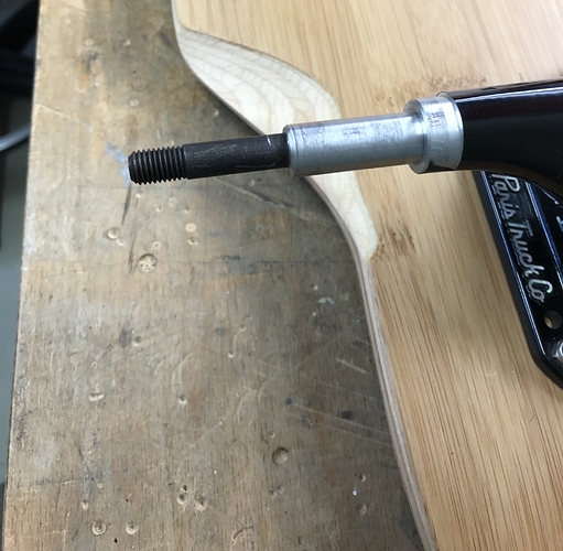
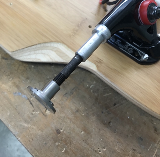
… and this is how the machined truck looks like.
In general there are three possibilities to prevent the stator from spinning due to the “reactio” moment. Positive connection, frictional connection or using adhesive (which is indeed some sort of friction). To keep manufacturing lean and simple because I want to give it a try I decided to go with a frictional connection. I use the mounting nut to exert the necessary force, pressing the stator endplate to the flange of the cast aluminium of the axle. To get a high friction coefficient the stator endplate is made of aluminium too. The power flow is transmitted from the mounting nut via the inner ring of the front bearing to the clamping sleeve to the stator endplate. Therefore the mounting nut and the clamping sleeve are made of stainless steel. Thanks to @ackmaniac’s app and @duffman’s recordings I was able to look at typical torques during hard riding. Accordingly, assuming a maximum torque of 20 Nm I’m pretty sure to be on the save side. I did a rough estimation of the maximum driving torque which can be transferred due to the friction connection in my current design. Glad it was almost an order of magnitude (!) greater than the assumed 20 Nm.
My first ridings confirmed that the stator did not move at all on the axle in any way. After that, just to be safe I additionally use some Loctite 638 for high-strength shaft-hub connections. Putting it all together the stator is locked to the axle by two independent means, each of which offering enough potential to do the job.
Disclaimer: I do not know what might happen to the joint when @Nowind get’s the board under his crazy feet. Happy he’s going only with eMTB’s 
Addendum: An important detail for the design is that the inner axle is uninterrupted inside the Paris trucks. I was afraid that it was two pressed axle stubs which can be pulled out of the castings by the mounting nut. Therefore, I have the truck in an X-ray machine for “non-destructive material testing” - lo and behold, one uninterrupted inner axle.
In the previous post you can see, that I provided the cooling slots with a very fine metal fabric (400um mesh width) to protect agains debris. Also made some more pictures on that and on the locking tool.
Thats all for the moment. Next posts will be about “Hall Sensors” and “VESC Mounting and Housing”.
Awesome work! Did You use CNC machines, or just manual ones? Personally I’m thinking about DIY hub set up from quite some time and posts like Yours motivate me to give it a try!
Just manual ones. At some point I was not quite sure about the tolerances, so some manual work together with intermediate testing worked out the best (btw I don’t have a CNC available).
This a truly awesome work.
I wonder if you are planing to sell a kit to be mounted on any outrunner motor, sell the complete set with rubber covers or share all information to the community so anyone can do it themselves?
amazing things on the forum lately, love your work and all the details! 
Currently I just want to share all the information so that everyone has the necessary background / prerequisites to give it a try. My intention is to get feedback from the community builds and eventually improve the design. Maybe we can take it to the next level.
Thanks! I always follow your work with great enthusiasm. I would love to have a @whitepony -like enclose on the bottom of this build 

This is the way to go! Really lookin good, but i hadn’t good experience with exact the same glue on my first attempt. Problem wasn’t slipping, but the urethane went off sideways from the can while carving. You have a flange on the inner side, maybe if you would build one on the other side too it may be better. Esthetically best hubs i know!
Thanks for the compliment! You had a smooth rotor can surface or also with circular grooves like from the older APS motors? Where are you from? I would be glad if a hard carver drops by and gives my build a try!
Almost smooth aluminium, just some scratches from a brush (so ne eisenbürste halt:), and alu is always shit to bond on… It may hold, hope the best for you!
Hall Sensors
Now comes the hardest part. If you have tried the VESC with FOC you won’t miss that any more. To get a good startup performance, hall sensors are mandatory. The easiest and space-saving alternative is to place the three hall sensors into the gap of the anchoring grooves at an angle of 120°.
If you are lucky, there’s enough space in between the copper windings and it looks like this after filling the gaps with epoxy resin.
This only worked with the second (spare) one of my motors. My first motor was used for the single hub motor V1. The design was as I already said “thermally suboptimal”. My son revealed that very clearly when driving at maximum throttle while pulling his friend on his skateboard … after a while the motor got absolutely hot so that the paint on the stator wires melted and stucked together. I had a hard time to dismantle the motor:
After unwinding the brick I had to Wye-rewind the motor  several hundred meters of wire but finally I got it made

I probably choose a wire with a larger core diameter (hard to estimate exactly because of the paint), so I probably got a very good copper filling ratio. Good for the torque but definitely too less space for the hall sensors in the gap of the anchoring grooves. So I had to take a different route using my Dremel 
Grinding has to be done carefully in order not to touch the windings. Since I had that much copper in the stator I wasn’t able to grind further as shown in the picture.
Fixed the hall sensors with epoxy resin, but finally they still were too much in height so they scraped at the magnets of the rotor. Again I used the Dremel to flatten the after I cut one spare sensor apart to see how far I can go.
Finally  https://youtu.be/MUvyfU1geIY
@The_Dude nice work, how did you managed to drill the wheel? I’m in a similar path of designing a hub motor from scratch, but it’s hard to find pourable urethane here, so using an available wheel would help, but in my previous experience working with urethane and keeping the dimensional tolerance was hard since it deforms easily


 Very Nice Stuff