Hello everyone. This is my first post. I bought for my sons xmas present Enertion components to build electric skateboard. Parts were rspec 6355 motor, space cell pro3 battery, vesc hw version 4.18, trucks, wheels, pulleys etc. Built on Xmas day and worked flawlessly, went out a couple of times and it was perfect. Charged space cell pro3 for next trip out on board and after the charge the controller wasn’t working. Took battery off board to start checks and noticed flashing red led on vesc, hooked up to bldc tool to check and found that the there was a over voltage error and motor detection did not work. Battery after charge was now inputting 45.6v into vesc and max input voltage was set to 42v. Changed this to 47v which cleared the over voltage error and the red flashing led stopped, but now on motor detection it fails and the motor just clicks and jitters around. Checked faults in bldc and it’s showing abs over current fault. Can any one help. Board was fine, this has only happened after the space cell pro3 was charged.
First of all you should set the max input voltage to 57V. This value is for the maximum the VESC can handle and not for the maximum the battery can handle. But a much bigger problem is that you say that the VESC realtime data shows 45.6v. Or did you see that in the terminal when you typed in faults. The maximum voltage that is allowed for the space cell is 42V because it is a 10S battery. If your reported 45.6v is really the case then you quickly need to reduce it by discharging. So please check with a Multimeter if possible and with the BLDC-Tool Realtime data. And if you want you can post all your settings of the BLDC-Tool here as Screenshots so that we could have a quick look.
can you post some picture of your setup… maybe some close up of the vesc, and also some screen shoot of your parameter inside the bldc tool.
Hi, thanks for you response. Yes it’s 45.6v in real time data. I also measured with multi meter and the 10s3p space cell is outputting this voltage. The battery LCD screen is showing 100% charged. I was expecting it to drop to 99% at some point but it has been like this for days. It hasn’t had a load on it apart from when I have done motor detects in bldc tool. How can I discharge it? I have nothing else at this voltage to connect to it to draw some power out of the battery. The vesc looks OK. No signs of any visible problems…solder joints all look OK and no sign of anything blown or overheated. Have checked motor connections and cables…they are all OK. Do you think it’s a battery issue. I agree with you that max charge is 42v on a 10s3p battery.
Thanks. I will post pictures and screen shots of my setup and bldc tool settings when I get home this evening. I am convinced it’s the battery as it’s showing 45.6v in bldc real-time data and with a multimeter connected to the output of the battery. Thanks
Which charger do you use? Please check it with a multi-meter if the voltage is really correct. If that voltage is really the case then you should bring the voltage down as fast as you can. For example by using the board with a very little load. Going very slow. And you should never charge the board to more than 42V ever again. Just find the root cause. I guess you used the wrong charger.
Hi, I used the standard charger that came with the Space Cell Pro 3 from Enertion. Not sure how I can discharge it as the motor will not spin correctly, just stutters, don’t want to take the chance of using the board like this. I have attached screenshots from BLDC Tool. Appreciate your help, this has only happened since the charge of the battery, so I think that when the power switch was turned on the vesc got 45.6V, it then generated an over voltage error, I then changed the Max Voltage Input to 46V which cured the error and vesc showed no faults, when I do a motor detection it then shows “abs over current error” the detaction fails but the motor does click and turn slowly.
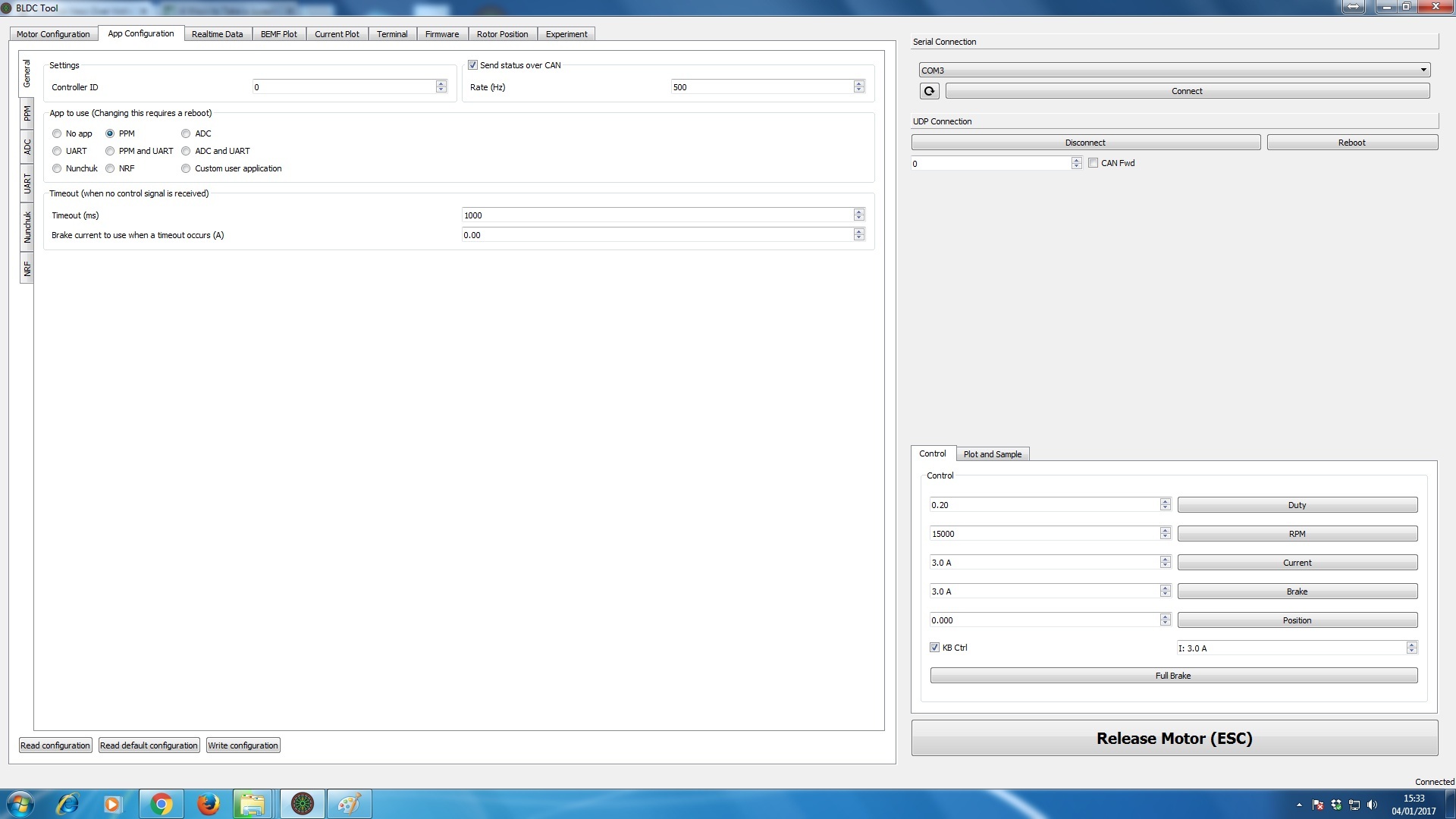

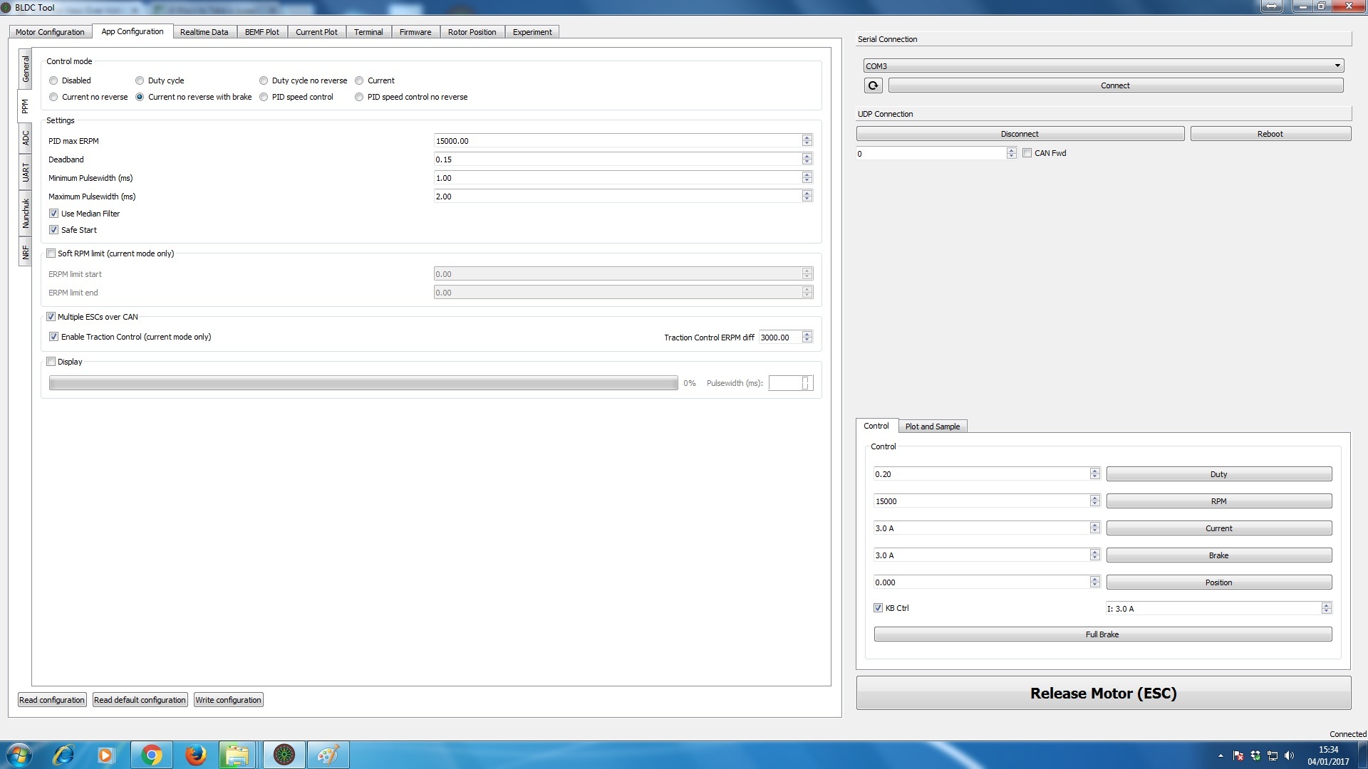


Set the max input voltage to 57V.
Hi, just checked the output from the battery again with a Multi-Meter and it is 41.2V, vesc in real-time data tab is now showing 46v. I am getting crazy results in terminal also…see below
Fault : FAULT_CODE_OVER_VOLTAGE Current : 0.8 Current filtered : 0.2 Voltage : 46.01 Duty : 0.63 RPM : 0.0 Tacho : 5 Cycles running : 0 TIM duty : 2642 TIM val samp : 131 TIM current samp : 2231 TIM top : 4200 Comm step : 5 Temperature : 25.54
Fault : FAULT_CODE_OVER_VOLTAGE Current : -0.5 Current filtered : -0.0 Voltage : 46.01 Duty : 0.63 RPM : 0.0 Tacho : 5 Cycles running : 0 TIM duty : 2648 TIM val samp : 131 TIM current samp : 2231 TIM top : 4200 Comm step : 5 Temperature : 25.54
Fault : FAULT_CODE_ABS_OVER_CURRENT Current : 114.5 Current filtered : 135.0 Voltage : 46.23 Duty : 0.00 RPM : 0.0 Tacho : 6 Cycles running : 20 TIM duty : 263 TIM val samp : 131 TIM current samp : 26505 TIM top : 52747 Comm step : 6 Temperature : 25.65
Fault : FAULT_CODE_ABS_OVER_CURRENT Current : 127.4 Current filtered : 144.1 Voltage : 46.35 Duty : 0.00 RPM : 0.5 Tacho : 8 Cycles running : 16 TIM duty : 263 TIM val samp : 131 TIM current samp : 26505 TIM top : 52747 Comm step : 2
Where are located?
Set max voltage to 57v, Still same issue. I have put a link to a video below showing the issue, it may help a bit more. I am thinking the vesc is not functioning correctly.
This is my 1st build, the vescs seem to be quite fragile after reading posts on here.
http://www.ivid.co.uk/ivid/downloads/20161231_192345.avi
I have emailed Enertion in the meantime. Any help and advice is very much appreciated as these things are not cheap and my 13 year old son is very sad that his xmas present only lasted a couple of rides and is now just a very expensive regular skateboard with no electrical power.
Thanks again
Hi, I am in the UK
The vesc came with a clear heat shrink around it and I noticed the power cables that are soldered onto the vesc had something underneath them which I couldnt quite see, i have removed the heat shrink and the insulation on the cables was damaged, looks like a knife has sliced the installation on both positive and negative cables, this must of been done when the vesc was put together then they just put the plastic heat shrink around the vesc. There are no signs of shorts or arcing on the board or cables, but still not good that the vesc came like this with damaged power cables.
Since you’ve already remove the heat shrink, do you mind taking some picture of the resisitor R3 and R4 (if you can also mesure them with a multi-meter), the shunt and the power cable ( to clearly see the issue you mentioned)
Thanks for the fast response, pictures below, you are right!!! Looks to me that there are quite a few resistors that are damaged/blown. I didn’t see it with the naked eye, had to zoom in on the photos. I guess this means new vesc, do you think the damaged insulation on the power cable s did this as they were tight too the board with heat shrink?

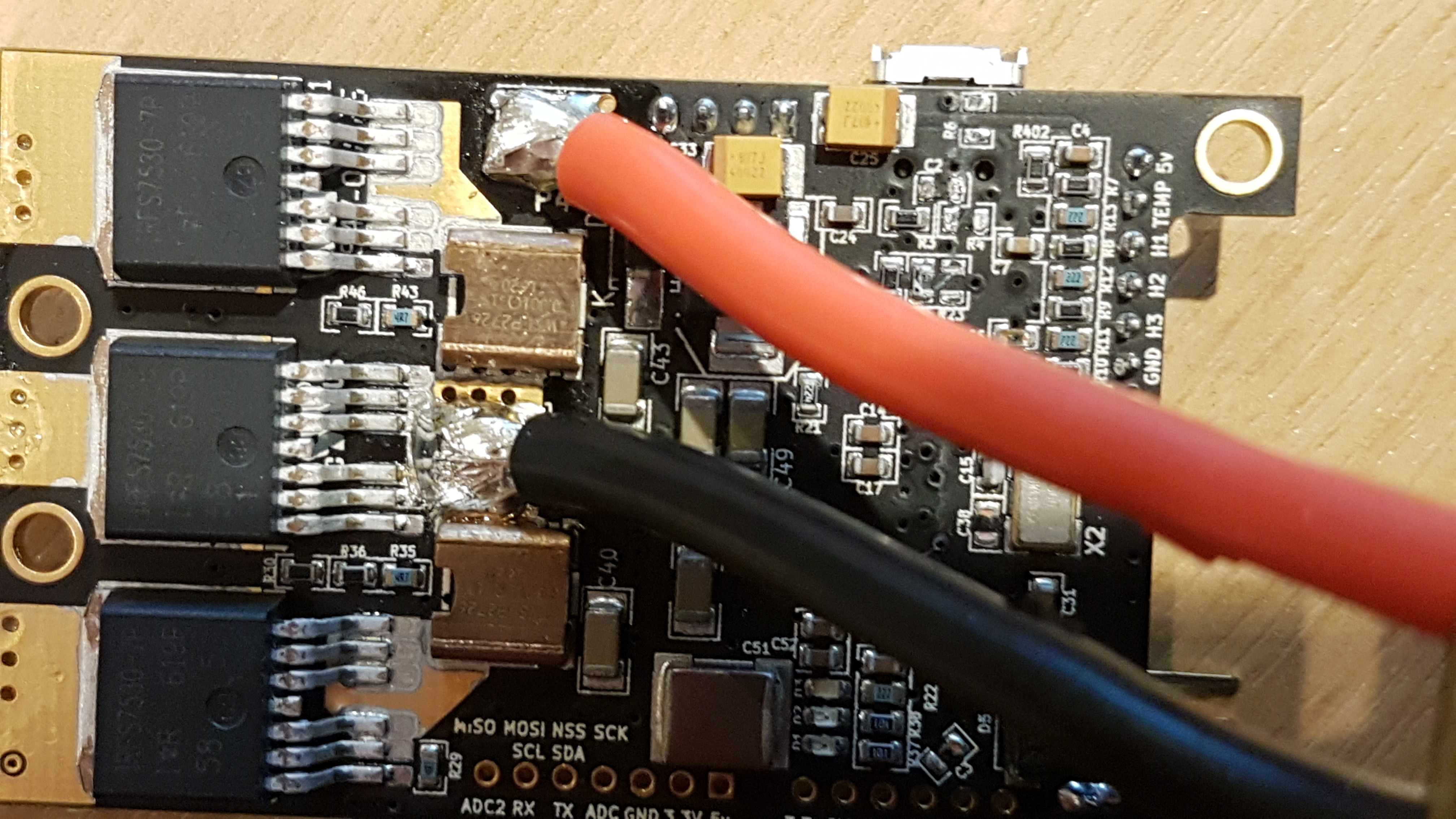

It looking like something hit the pcb.
Yes I agree, Obviously new vesc required. Thank you for all your help, at least I know what its is now.
Well if tou have access to a good soldering Iron, it is not a really hard fix. But if you want to be safe I suggest you to contact Enertion support.