Hey Kids,
Intent: This marks the beginning of a multi-month ground up build. I will be attempting to create a electric freeboard almost entirely from scratch. I will periodically post my progress here, as well as links to relevant articles, my CAD files, and my motor control Code.
Background: I am a Senior in Electrical Engineering at Purdue with a heavy background in parts fabrication and controls. This summer, I am interning in Detroit, and my company (omitted), also encourages personal projects that double as learning experiences. Thus, inspired by the LEIF board, an idea was born. What if I could completely design, fabricate, and program an electric freeboard from scratch for under $1000?
Thus far, I have CADed a proof of concept, begun my second design iteration, have started performing calculations for desired Motor Spec, and have created a (pseudo)-working control algorithm for a 3-phase brushless outrunner I had lying around.
Lets start with my proof of concept.

Before you say anything, I know that it looks pretty jank, expensive, and overly complicated. The intent was to demonstrate a working design to get funding before moving on to the next couple iterations.
Here are a few more pics:


This design featured off the shelf parts to enable the wheel pods to rotate, mostly a 200lb lazy susan, and a 3 lead, 30 amp slip ring which would allow the passage of current to the pod, without having to worry about leads getting twisted. Additionally, it made use of two, 18" Carbon fiber rods and a series of belly pans to create a superstructure allowing battery mounting and mounting of the control electronics.
This design has several problems.
FIRST: It’s expensive, It’s heavy, and overly complicated. The carbon fiber alone would cost about $170, which is too much for (at best) a medium amount of flash. The Aluminum wouldn’t be too expensive itself, but as i no longer own a waterjet, I would need to pay someone to waterjet it for me, which would not only cost more money, but would also dent my pride 
Furthermore, 30 amps is not nearly enough to drive these motors, which usually are happy around 60-70 amps each. I looked around online, and couldn’t find a slip ring that would fit my design for less than $750 each. So again, no go.
So, scrap that. She was pretty, but not feasible.
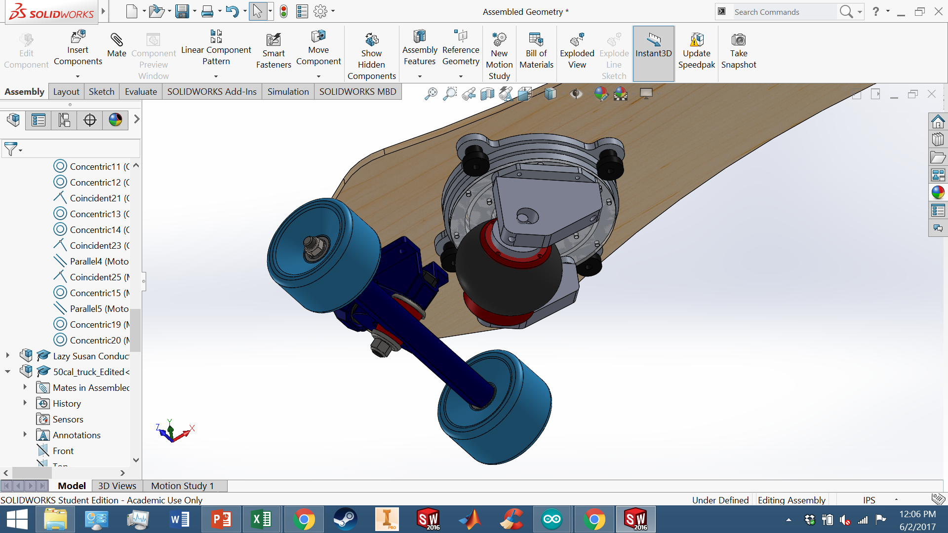
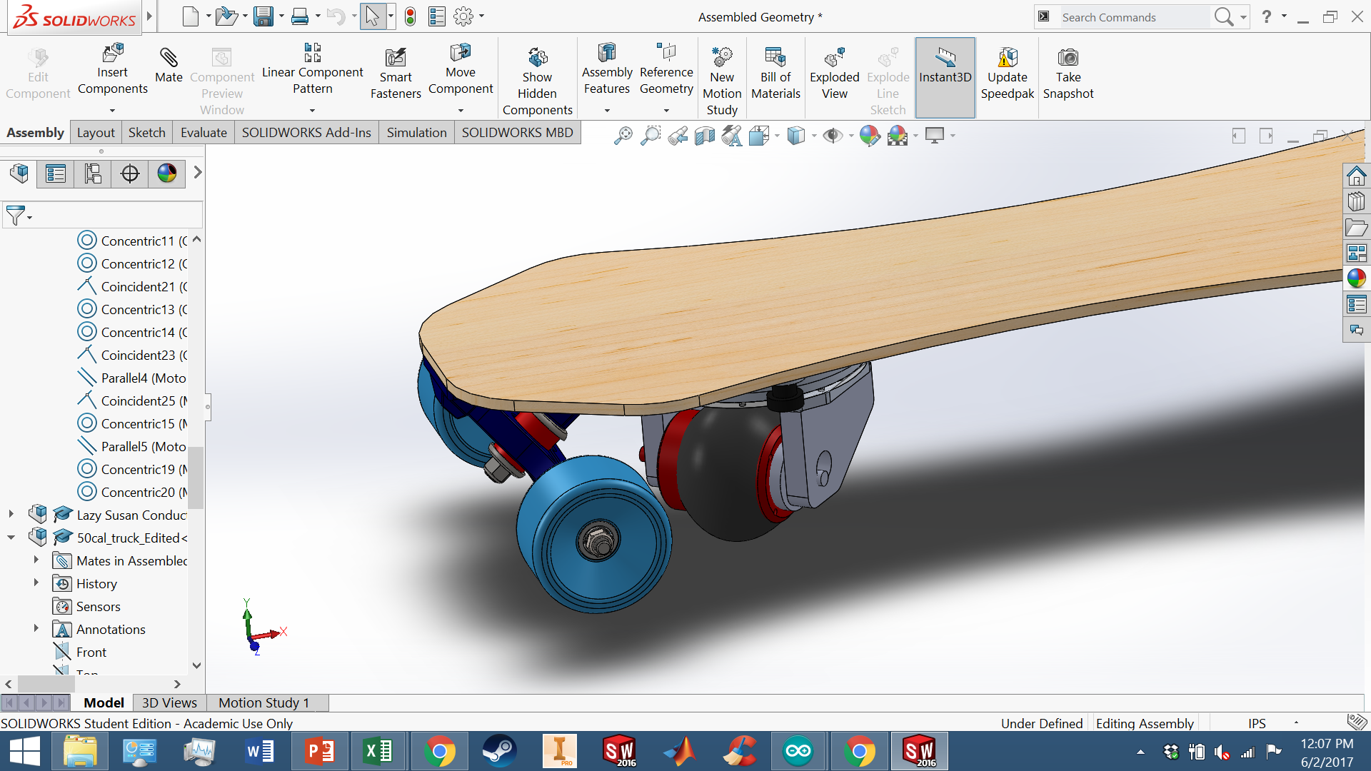
This brings us to my second design iteration.


This design features a custom-made, combination slip-ring lazy susan and a wheel mounted directly to the exterior of an outrunner. As seen in the first picture, the lazy susan comprises three stages, each electrically isolated from the others, which doubles as a slip ring, allowing individual currents to pass through each of the three “phases” to the corresponding phase of the motor.
This design has not been flushed out yet, but that’s kind of the point of an ongoing blog right?
On to controls.
I plan to utilize an arduino uno to pass PWM signals to the gates of a standart MOSFET array, allowing current to flow into each phase of the motor in time. A great synopsis of this, as well as the control theory behind brushless motors, can be found here: http://electronoobs.com/eng_circuitos_tut4.php
I actually plan to follow his process quite closely, finally diverging in the speed control stage. Rather than use a delay between phases (which will result in somewhat choppy feel) i will use PWM control to modify the duty cycle of the motor, allowing speed to vary that way.
Thus far, I have built my array, and flashed my arduino.


However, When i execute my code, i have no way to determine the position of the rotor, resulting in a high level of shoot-through and reverse driving. I’m overworking the FETs i have, and am not able to produce the smooth drive action i want.
Thus, as any electrical engineer does, I need more sensors.
I plan to buy two motors with hall effect sensors that will allow me to monitor the precise position of the rotor relative to the stator, and create a much smoother motor drive.
However, before i can do that, I need to buy motors, and before i can buy motors, i need to pick them.
I am thinking about running a 4 cell set up. The batteries i have are 61 amp hours, so they’re massive, and can push any amperage i could ever want. But they’re big. Thus, i will use a higher Kv motor, at a lower voltage to achieve similar results to those i would get with a lower Kv motor, and higher cell count.
I have run the math, and it looks like i should be able to hit about 25 mph with 4 cells and two 2000 watt 270kv motors. It’s also noteworthy that I will be using 78mm casters.
I can’t obtain any torque curves for these motors, but i think that they should work. Any feedback from people with hands-on experience would be great.
That’s all for now!