I’m almost done my personal build, but I’ve noticed one part that goes fairly undocumented in most builds despite being almost vital: The fuse. I’ve seen suggestions to use a 60V 10A fuse, 60A fuse, fuse on the negative charge wire, fuse on the positive battery wire, and everything inbetween. Could any experienced builders explain why they chose the fuses they did on their builds, where they placed them, and why?
@Creavenger you don’t need a fuse between the battery and the vesc, but a 8-10a fuse on the negative of the charge port is never bad.
4 Likes
yes it is still better safe than sorry.
2 Likes
I agree with both of the above answers. You don’t need one as the bms should do its job and cut off current in overload situations. Fuses are also dirt cheap and offer more protection.
Then again… I run unfused (except negative side charge port) with a charge only bms and rely on my unity vesc to be able to shut and and take it. No issues so far.
2 Likes
My reasoning and specification for fuse #1 would not be an overload situation but a short circuit or thermal runaway. Protecting a battery from faulting into a short circuit.
#2 fuse, why place on negative lead? Edit to add, I don’t think fuse 2 will protect from a charger malfunction in all cases. The charger could pass 4A and overcharge the batteries all day. Again I see it as a short circuit protection on accidental short at the charge port or also an overload in the smaller charge wires.
2 Likes
If fuse #1 lies between the battery and the vesc, how would a blown fuse protect any more than a blown BMS in a short circuit scenario? If your battery shorts itself, you’re in trouble already.
Current is flowing from battery to BMS (set to cut off at over current) to Fuse #1 to VESC to motors.
Nothing is back flowing to the battery in this case except regenerative braking which we aren’t talking about.
This is where fuse #2 comes in. It won’t protect against all malfunctions. His job is to make sure that if your charger flips its shit and starts outputting 30A somehow, your battery doesn’t get charged at the incorrect rate. It blows the fuse and your board is no longer charging. Your BMS can also F up and start charging cells at the wrong rate. Nothing is perfect, just aim for the safest you can.
Negative side charge port is @b264’s recommendation that I just regurgitate from time to time.
What part of Ohio are you out of?
2 Likes
I’m northeast Ohio east of Akron. Are you around here?
I’m saying I’m not worried about protecting my esc. I’m sizing my fuse based on a shorted fet, melted connector at the esc, etc. Something that would cause the batteries to dump current into a short circuit resulting in venting batteries and flaming balls of plasma. I would spec this fuse well over the overload range of the esc. I would spec it somewhere below my batteries short circuit current ability but we’ll above my esc current capability Like 200A time delay.
Just because a bms or esc is set to cutoff at certain current levels, does not mean that during a fault or component failure it will reliably do so.
I still see #2 as protection from shorting your charge jack. Is it known in our community for a charger to fail in such a way as to over current to the battery? I think it is more common that the jack gets shorted.
I think it is important to understand what faults or equipment we are planning on protecting before we prescribe a fuse. This comes down to user preference and best practice. I agree, no reason not to fuse charge port at slightly above charge current. Fuse 1 we must decide what we are protecting against. Is it equipment overload or short circuit.
I like a fuse on pos and on neg, this way if your battery is in a good mood you protect the happy and loving electrons, or if it is angry you protect the little deviant bastard electrons. Conventionally speaking anyways…
1 Like
Cinci area so direct opposite 
Ok we can agree on many things here. I am using the fuse rating of the wire to attempt to accomplish the same task. I am running case #1 without a traditional fuse to allow equipment overload momentarily but still able to hopefully prevent a short from occurring. I personally like to have a fuse built in to the battery positive charge circuit as well for extra protection but not all battery makers are implementing this.
I have hesitation about using wire as fuse such as in the cell level fusing. What gauge wire are you using? And what would be the expected melting current. Maybe I could try a real world test.
I am having a little fun with the pos vs neg side fuse, I would be content with one.
I actually put my loop key in the middle of my battery, so it is like two 5s packs series’d together by loop key. I was thinking of using a fuse there. I am trying to think if there would be any benefit there if there was an internal battery short.
10 gauge but very high quality wire. Silicone wrapped so it doesn’t melt even when a soldering iron touches it. Inside stand count is in the thousands. Loopkey in the middle is an interesting concept. I need to think about that one for a minute. So when you plug it in, you have the end opposite the loop double paralleled out to your packs? Assuming yes for a moment, would that really do any difference to in rush current? 18650 packs of multiple p groups are doing this on a smaller scale to the bms but with a board between. I’m approaching the limits of my knowledge and re-entering the learning field.
Hyper drive, engaged
Fuses help to protect stuff when you decide to connect your battery with opposite polarity… @Creavenger 
Within my 7 years of working with the high voltage system in electric cars, I have seen countless of times where a fuse is a good thing when working with prototype parts. I take all that knowledge with me home.
For me the loop key is the fuse and it is placed in the middle of the pack (It just felt better having the pack divided in two when not used). I pretty much agree on everything @MD84 has said 
1 Like
Guess im installing 2 fuses 

1 Like
so when i want to use a charger for my upcomming 12s5p pack with 4amps and 50.4V
would be a 5a or 6a fuse like those are ok or do i need to take smthg else?
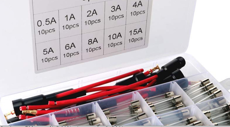
If you look at the silver end caps of those fuses you should see the voltage rating. I’m guessing those are not rated for 50v. One thing to consider is that even though the fuse element may melt, this will draw an arc. The fuse needs to be able to quench that arc. Many fuses employ a spring or otherwise mechanical means of separating the electrodes sufficiently to create an air gap for the voltage if the system. Some fuses are filled with sand for example. If the fuse cannot extinguish the arc, it is possible arc could persist and lead to further faults and damage.
Long story, size a fuse based on the nominal system voltage and desired current threshold. Also it is good to consider reactance and short circuit ratings. For example motor loads or capacitors exhibit reactance in which a large current initially flows for a very short time. In this case you would want a time delay fuse. The time vs current curves can be referenced for more details. For a constant linear load a fast blow fuse can be used. Available short circuit current is also a consideration. If the battery is able to deliver thousands of amps it is possible the fuse cannot break that amount of current and will fail allowing fault current to persist.
These considerations are partly why I question using wires as fuses. If we have a silicon encasement around our melting conductor, how does the current break if the molten copper is contained?
1 Like
yes youre right theyre not rated for 50v but there are some rated for 8a and 60v what are other people using here? im talking about the chrging fuse kr
This should work
https://www.amazon.com/Baosity-Overload-Protector-Resettable-Waterproof/dp/B07H3V23J7


2 Likes
thx very much man gonna build this into my new integrated deck
For Science
2 Likes
What fuses should i get? I have a bms with a continuous dischage current of 40A, the esc can handle 60A continuous and max 240 for a few seconds, I’m running a single motor setup so i was thinking about a 80A fuse between the battery and esc. And I was thinking about a 7.5A fuse for the charge port (on the negative wire?).