[HELP]:VESC not reading Arduino PPM signals correctly, but reads hobby RX correctly

Hello, I was building the nRF24 Remote Controller by Solidgeek. But then, I realized that VESC was not receiving the PPM signal correctly. It was lagging by about 0.2[ms]. So when I hooked up a oscilloscope, I saw this.

<Analog Write(128)>

Period = 1 millisecond 128_pulseView_period

Pulse Width = 516 microsecond.

So… you would Expect to see a value of around 0.5 ms at VESC Right???

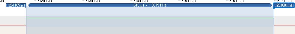
This was seen from the VESC side.

128

0.721 milliseconds. That, was clearly wrong, as I verified the width to be around 0.5 ms beforehand…


So what is going on??? I was eager to investigate this problem further.

I hooked up the ‘hobby RX’ to the VESC, which has been working flawlessly for the past 6 months. I gave a Middle Signal and MAX signal as an Example.

Stick position : Middle

solid 1500 microseconds pulse as Expected.

Stick position : MAX

MAX_pulseView_verify(1999)

solid 2000 microseconds pulse also.

AND, when seen from the VESC, it is also correctly perceived.

Stick position : Middle Middle Stick position : MAX MAX


So I got confused here. It can’t be true that VESC looks at the same pulse, then perceives it differently…

And I wondered Maybe it is because analogWrite( ) doesn’t have long enough period(ex.20 ms) between two pulses. If you look at two pulses, they definitely have different period as you can see.

analogWrite(128) 128_pulseView_period

Receiver Middle

I thought, that MUST be the problem! And tried another code.


Arduino has a library called ‘Servo’, and it is able to output EXACTLY the same pulse as commercial hobby receiver does.

Let me show you the two pulses side by side.

Top is hobby Receiver, Bottom is Arduino

They look exactly the same! Same period(20 millisecond) & same pulse Width(1.5 ms)…

With my hopes high, I hooked the Arduino to the VESC And… drum roll please…

Using Arduino Servo Library

1500

Nope, VESC says it is ‘1.7 milliseconds’…


At this point I was very much confused. This time, VESC actually is saying two Same-looking pulses are different…

I have tried another Method using Timer2 of Arduino, and it did produce somewhat legit pulse.

Using my own Timer2 code 1500_pulseView_period

It does have a shorter period, but the pulse is almost spot-on the 1500 microseconds. Yet, VESC reads it as…

Timer2 code pulse, read by VESC 1500

And the above result(1.7 ms) is very similar to the value I got from Servo Library test(1.7 ms).

And I think there exists a reason to it. But can’t figure out what it is…


So conclusion from my own investigation is

  1. VESC perceives same-looking pulse from hobby Receiver and Arduino differently.
  2. VESC is able to pick up 1[kHz] signal(analogWrite), but reads it off by 0.2 millliseconds.
  3. VESC reads both 15ms period & 20ms period Servo signal with width of 1500 us, but reads it off by 0.2 milliseconds. So VESC doesn’t really care about the PERIOD of the signal.

So I am asking for help. If this issue is familiar with you, or if you have Any suggestions, ideas or thoughts, I would really appreciate the comments. Thank you for reading my Topic :slight_smile:


p.s.) I actually have done further tests and found out that analogWrite(x) is not read properly by VESC if x is more than or equal to 182. If I go higher, VESC just gives up, and PPM value doesn’t get updated… I have no Idea why that doesn’t work.

analogWrite(182) viewed from Oscilloscope

182_pulseView_verify(732) => It has about 732 microseconds of width.

analogWrite(182) as read by VESC

182_wontGoFurther

=> Tops out at about 1 milliseconds. Which is the period of the signal, actually.

1 Like

This has been corrected in the development branch on github. The analogWrite() function produces a PWM signal and not a PPM as expected by the VESC. To produce the PPM signal, the Servo library can be used instead :slight_smile:

EDIT: I didnt read the entire post before answering, I see that you have already tried using the Servo library. Could you try using my development branch, and make a new test?

1 Like

Couldn’t tell you why this happens exactly but can say I’ve seen similar values using the servo library to write microseconds values to the vesc. Personally just adjusted the endpoints and deadband to deal with it but would be interested if you figure out what’s going on.

Simple controller code without the bells and whistles here https://github.com/shusain/eskatecontroller can uncomment the debug define to activate serial, keeping it off seemed to help with general speed of updates.

1 Like

Wow, a LOT has changed from master branch!!

I will have a look at your code first and then test it.

This is because I have modified the code to use the software Serial on Receiver to talk with VESC, so I need to change that part :slight_smile:

Me too, I have no Idea why this happens… :frowning: And I have also adjusted the endpoints to 1200 ~ 2200, and that is working fine for now.

Thanks for the link! Your etched pcb looks cool, I have never done that before. I might try that :slight_smile:

1 Like

It is fun to make your own but also a tedious process and really annoying when you have to repeat steps after the first few times of doing it the novelty wears off :slight_smile: .

If you’ve got some time though it’s fun to do, I used EagleCAD to make the schmatics/board design and then laser printed and iron transfer the toner to the copper clad (sometimes transfer doesn’t work great then need to print and try the iron on again or use a sharpie to fill in the gaps by hand) then etch in ferric chloride (have heard of people using some HCL mix as well but think you need to get the timing more accurate with that method of etching).

Instead of doing the toner transfer method you could also get some UV sensitive masking and use transparencies of the schematic (inverted) to cure part of the masking onto the board before etching (I’ll probably try this in the nearish future). Right now neck deep in building an mpcnc in part to see if I can just route out the traces on a PCB and skip all the transfer/etching steps but hopefully at the very least can use it for doing hole patterns on PCBs (and other stuff).

Ultimately ordering them from a professional PCB fabrication house is the way to go since they can turn around in like a week or two and will be better quality and pretty cheap but when playing around it’s nice to be able to make your own (relatively) quickly.

1 Like

I just read the whole transmitter code. (It was pretty confusing around setting Loop flag & change flag & stuff… :frowning: )

I really like

  1. ‘change Address’ and ‘change Mode’ feature synchronized with the receiver
  2. continuous scroll when changing value inside the setting
  3. having a variable called ‘throttlePosition’

And I have proposed 2 small pull requests to your development branch, if you have time check it out!

Now I will read receiver code… and then test the whole system!

1 Like

Wauw thanks, glad someone takes the time to look it through :slight_smile:

Yeah I am having a hard time understanding that part myself, I plan to rewrite / or do some heavy commenting on that part later. Glad you like those feaures, I will give your pull requests a look in the coming weekend.

Looking forward to hear about your findings!

1 Like

Um, until now, this is what I observed.

  1. Servo pulse does work, but gives 1.7ms when Middle. But adjusting the range in bldc-tool can solve the problem.
  2. I do have solid signal on the default address (e8e8f0f0e1).

But, I do not have ‘switching Channel’ function operating correctly. I do think that I might have modified some parts(like delay(100) ), and is why this is happening. I will test again tonight and tell you the results.

Slight suggestion : in the Remote Hall Sensor min/max setting, just let user position the thumb-wheel and capture that data. (But I’m not sure how to implement this right now).