@psychotiller - any chance you can look up order 9204255? I really need those wheels to continue the build and they were ordered on the 28th and still haven’t shipped. Thanks.
I’m trying one kind of like this: https://www.electric-skateboard.builders/t/wtf-is-this-unknown-build/31121 sort of like this: I’m planning on pairing a set of those trucks with a "29 jet Spud. I’m still trying to figure out how to attach them to the deck without drilling extra holes or putting unnecessary stress on the deck.
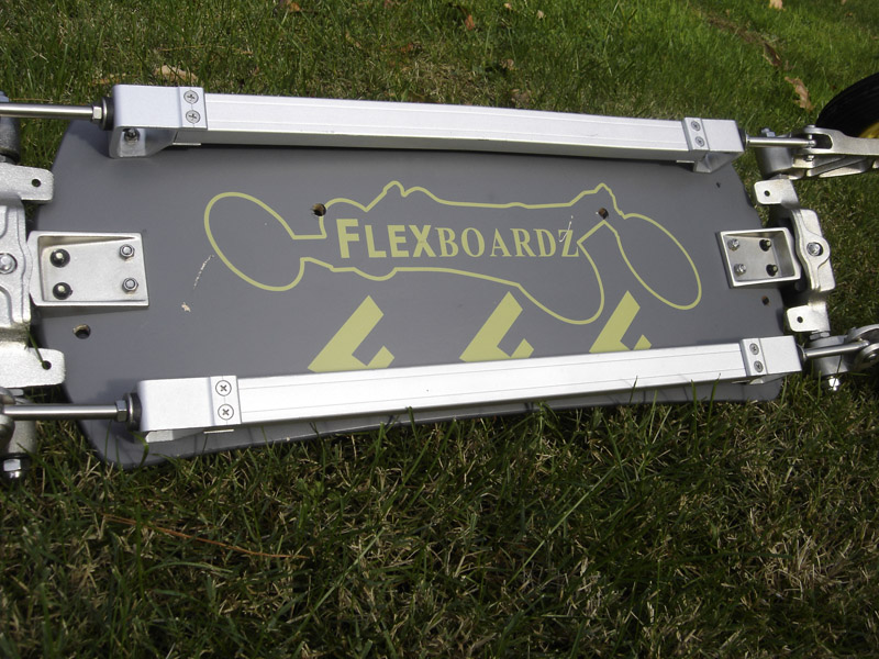
@High-roller Looks pretty easy - you just need a big block of aluminum for the holes for the upper and lower control arms, then you can transition back to a regular skate truck pattern, like flexboardz did here:
Are you building the suspension from scratch or did you find one on eBay?
2 Likes
I bought BMW streetcarver-style trucks from a guy here on the forum. I was thinking I’d 3d print the plate like you mentioned, instead of making it from aluminum, in order to save weight and cost. Since the original holes were spaced out wider I’m worried that using a plate to bolt it to the four standard holes will concentrate the steering forces on a smaller area, possibly causing more mechanical stress to the deck. What do you think? (Bty, my apologies, I didn’t mean to hijack your thread)
I’d have to see pictures of what you bought to know exactly what to recommend, but If you are 3D printing what I think you are 3D printing then that will blow apart long before the deck does 
You can sandwich the board between thin(ish) aluminum plates to distribute the forces. Think of a standard skate truck riser but instead of being the same size as the truck it’s maybe 3/4" larger on all sides.
So it’s becoming a thing!
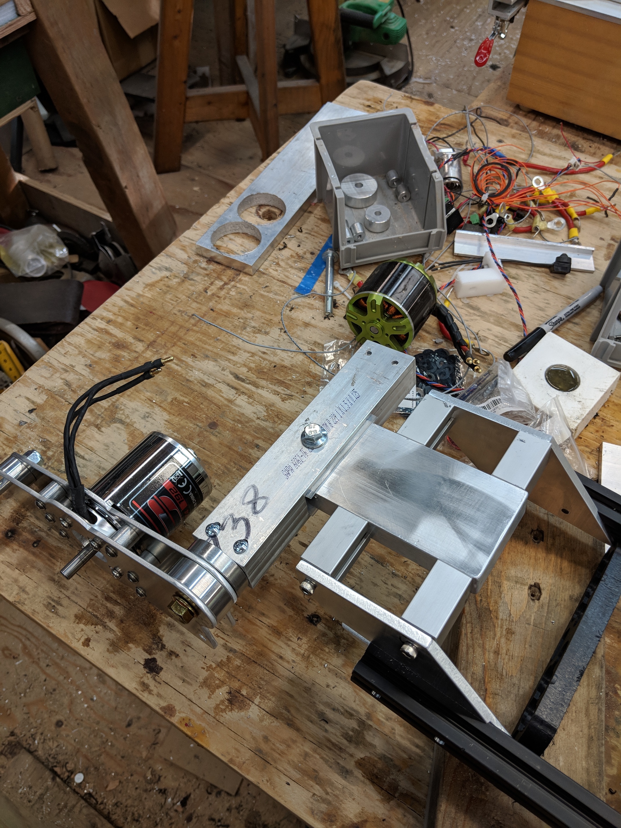

I knew I was going to have to rework the trailing arms because if I want geared drive the motor needs to be closer to the wheel, but also in looking at the way it goes together the lower link needs to be horizontally in line with the suspension bushings or it will either twist or bind up. So that has to be moved (or depending on how squishy I want the suspension to be I might add a drop plate to line them up.
In the meantime I can always belt-drive the wheel (I think the Psychotiller’s come with belt cogs) just to get it on the road. I am also going to put a standard truck on the front just so I can test the rear in the real world. If I need to make changes I only want to make them on one end, then when I have it perfected (or approximated) I can reproduce for the front end.
But the real test is whether the thing turns at all or whether I’m making a huge pile of aluminum scrap. With luck that question will be answered next weekend.
7 Likes
I went on a group ride on Thursday and there were 2 people there with mountain boards - In talking to them I’m pretty sure I under-spec’d the size of the tires, so I’m switching up from the 6" pneumies to 8" pneumies.
I’m going to try to get the gearcutter up and running this weekend - if I do I’ll post a vid if I can, or piccies if I can’t.
Do u think your system might allow some form of shock absorber to be installed?
I imagine if tilting arm gets fixed in place with shock absorber it might absorb road vibration / irregularities as well
Yes you can put bushings on the lower link. If you look at the FlexBoardZ suspension you can see the rubber bushings in the right side of this picture:
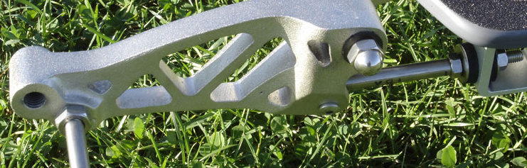
I was planning on starting with various types of skate bushings and then go to springs if I need to. Fortunately the way my design came together I have tons of space available in that area.
5 Likes
I know all y’all have been wanting to ask me, “but Doug, what happens if you accidentally go on Criagslist just to see what’s there?
Well, I’ll tell you what happens, you come home with this: Mostly I just wanted the trucks, but actually it’s a really nice board.
In any event the wheels are 8" which is my target diameter. So this represents an opportunity to get going on the spinning mechanicals at the same time I can keep working on the trailing link suspension.
Now I just need to figure out how to mount motors to those trucks. That’s my goal for tonight and tomorrow night.
3 Likes
So I got the bracket figured out for putting the MBS Mountain Board trucks on the Doska. It’s 21 degrees, which seems to be what the MBS deck angle was. (correct me if there is an official angle for these things that’s other than 21)
It shouldn’t be that difficult getting this up and driving around - I don’t see any big blockers. Probably, honestly, I’ll play on it until fall and then switch it all out for the trailing arm suspension for a spring debut.

I’ll throw the MBS wheels up on Thingiverse but the truck is kind of an embarrassment since I didn’t have time to model it up properly.
I ordered some Delrin to make the cogs. The MBS drivetrain will be chain drive since they are temporary - I’ll focus on the gear drives for the trailing arm version. This is the cog to mate to the MBS wheels.
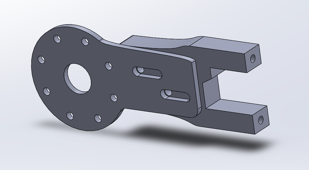
I also got a basic motor mount worked up and 3D printed a test - it looks pretty good so I’ve got some aluminum on order to make those. I don’t want to make the final motor mount until I can actually bolt the cogged wheel onto the truck so I can do some chain length reality checks.
2 Likes
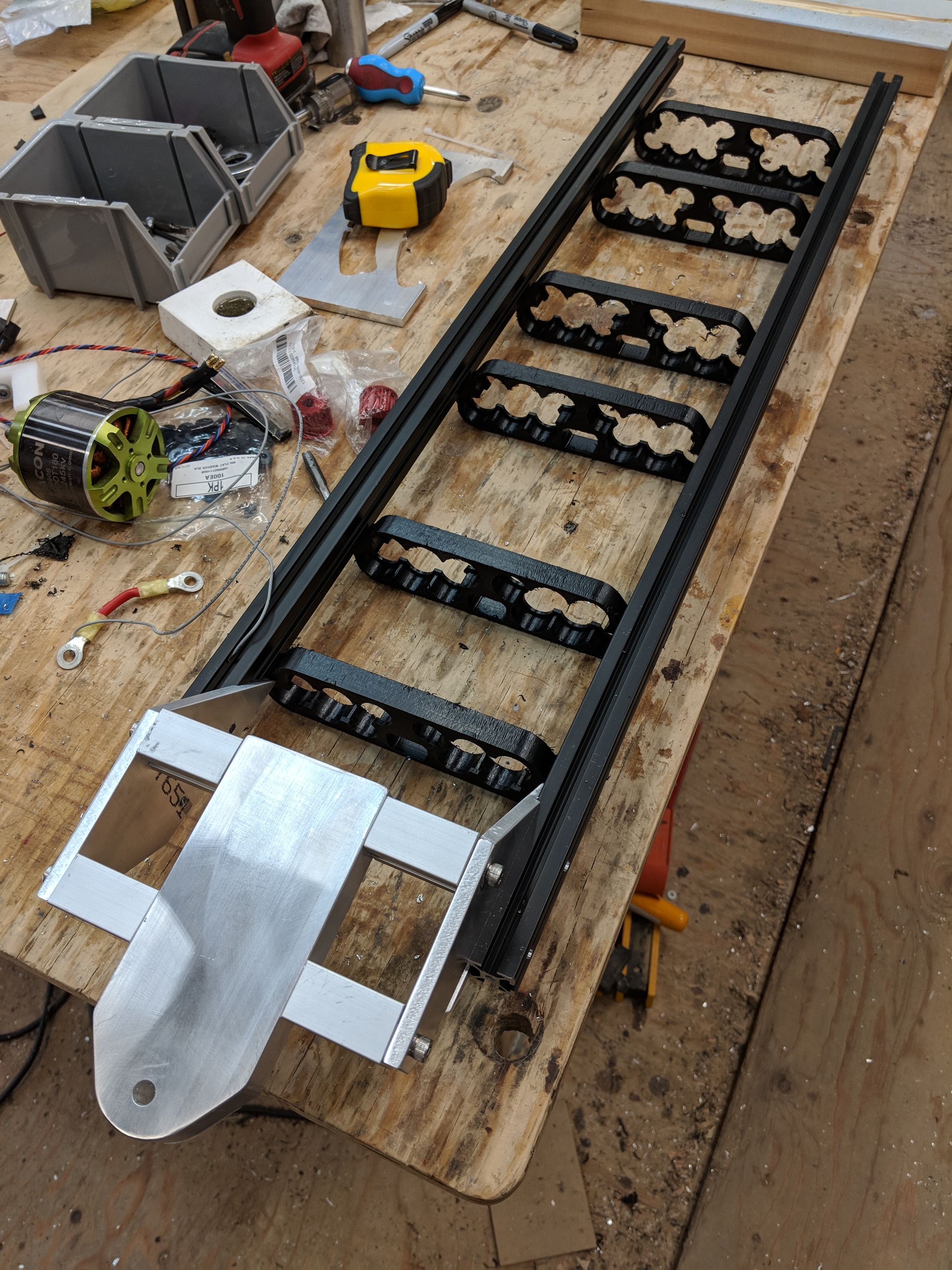
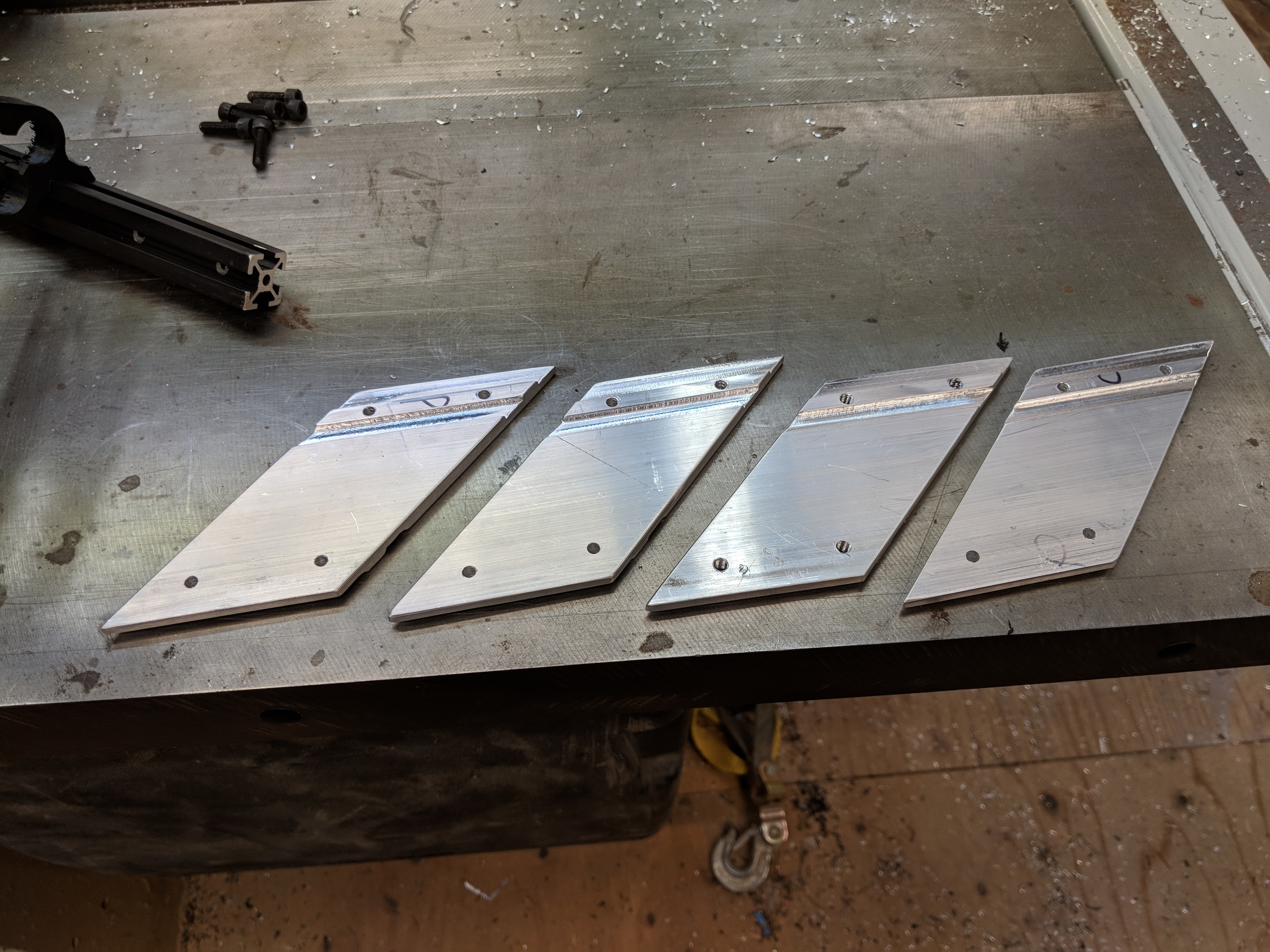
The weekend got away from me but I did manage to get the risers made.
Unfortunately some of the metal I ordered is on backorder so I’m not sure when that will arrive, but the Delrin should be here tomorrow. BUT. . . that might not do me any good because my little tabletop CNC mill might not have enough Y-axis distance to make the cog. It’s 5.6" and the table range is 5.7" so we’ll see if I can squeeze it in there without hitting the hard stop.
UPDATE: I can do it! I manually moved the Y axis all to the way to the end, backed it off a half a turn, then powered it up and test-ran the pattern and it didn’t hit any of the hard limits. Score 1 for the little Taig!
1 Like
I know all y’all have been wanting to ask me, “but Doug, how the hell do you make chain sprockets anyway? Well, I’ll tell ya, it’s kind of a hack.
So my chain is ANSI #25, which basically means it’s about half the size of bike chain. Getting the chain isn’t too difficult, but it’s kind of tricky to find a chain breaking tool, but they are out there. I ended up making my own, but that’s a much longer story.
So to start with you have to go to one of these cool esk8 calculator sites and decide on your gear ratio. I gear all my boards, more or less, for 25mph. This seems to be the sweet spot between enough power to climb hills and slow enough so I don’t die instantly.
My current board has 4" tires, for the sake of this calculation I want to reproduce the exact same gear ratio only for the 6" Psychotillers (those of you who don’t have a life and have actually read this whole thread will realize that this is a complete diversion from the 8" MTB wheels I just got. This is because I really want pneumies on Widowmaker, I already ordered the Psychotiller wheels and all my aluminum and Delrin for the Horská doska build is on backorder. So here we are.)
So it just so happens that you don’t really need to do a lot of calculatin’ to figure out that 6" is 150% of 4" so you just take the number of teeth on your current board and multiply by 1.5. My current board is 11:34, so the new board is 11:51.
But let’s say, like me, that math isn’t your strong suit. Then you can just go to this esk8 calculator website:
and enter a bunch of numbers. Here are mine for Widowmaker:
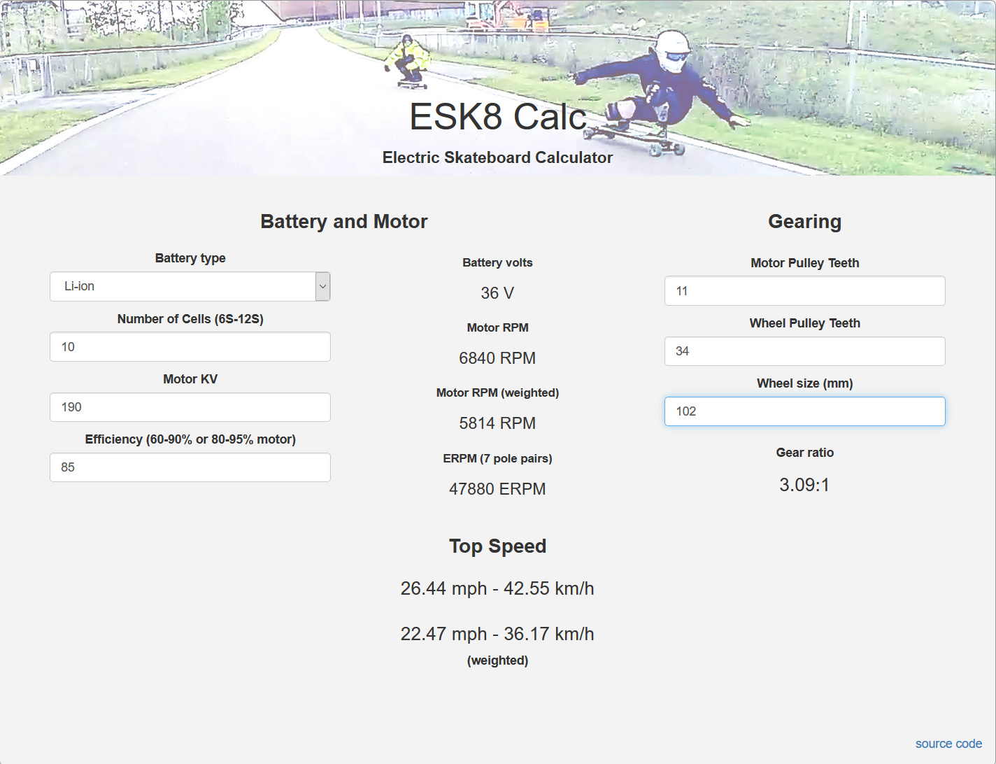
So my top speed is 26.4 mph. Now change the wheel size from 4" (102mm) to 6" (153mm) and then just ditz with the Wheel Pulley Teeth until the number is about the same:

Ok, so now let’s make the cog. Go to this website:
http://www.idleamusements.com/?page_id=367
and super handily in the “Common Chain Sizes” table it tells you everything you need to enter except the number of teeth. In our case ANSI 25 is 0.25 Pitch and 0.13 Roller Diameter.
Now just enter the number of teeth (51) and hit the “Submit” button.
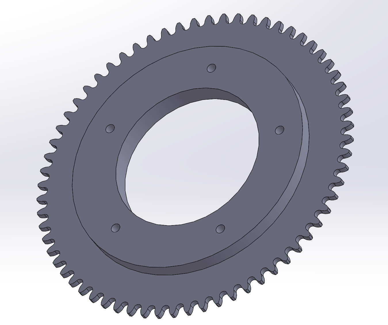
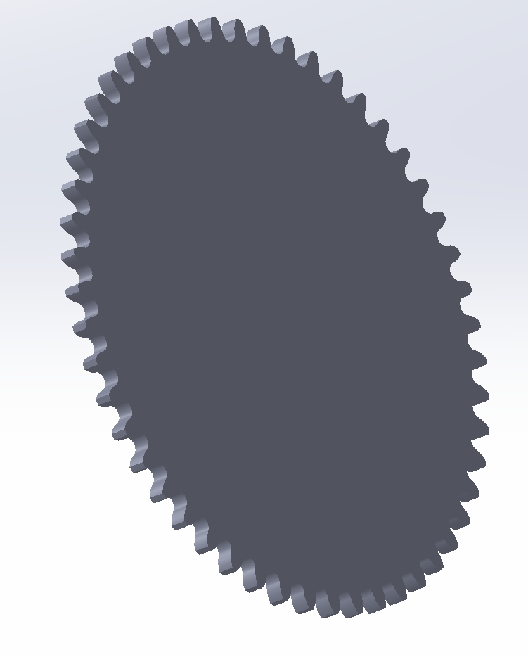
What you get is a DXF output and a GCODE output. Download the DXF output and load it into your favorite 3D manipulation software (mine is Solidworks because work bought me a license) and what you get is something like this:
The inside width of the chain is 0.125, so I extrude the gear out to about 0.120. (it actually doesn’t matter since I just turn it back into a 2D DXF when I put it in my CAM software).
I don’t like the pointy teeth, so I remove an arbitrarily small amount from the edge:
The particluar Delrin I bought is 3/8" thick, so I add the thickness back in a little bit in from the teeth.
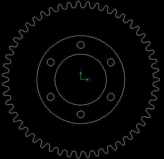
Now add the holes to attach it to the Psychotiller hubs, which are a 6-bolt pattern about 1.895" apart. They are either 10-32 or M4, so using a TAP and Drill chart (https://littlemachineshop.com/reference/tapdrill.php) make the holes 0.1960". Also add an arbitrarily sized center hole. Mine is 1.4" Dia.
All said and done it looks something like this:

Export the thing back out as a DXF:
And you’re ready to CAM. That’s another post.
3 Likes
Got the truck brackets made. It required a bit of imaginative and foolhardy fixturing to cut the angles:
 Kids, don’t try this at home!
Got the brackets and trucks mounted on the frame but didn’t have time to put the wheels on. I still need to do something about a deck. I’m seriously thinking of doing bigfood pads instead of a standard deck; Something derivative of this:

I CNC’d the driven cogs:

But I still need to finish them out on the lathe.
I’ll definitely have a rolling chassis by the weekend. Maybe get some battery packs welded up but doubtful it’ll run under its own power. There’s still a long ways to go especially since I’m waiting for the FOXBox Unity to ship.
1 Like
I never completely understood how the flexboard works. Especially since it can carve so steep.
So basically the swing arms can… emm swing. And the actual steering happens in the main block that hold the swing arms and is bolted to the board. And then the underside has just reinforcements running on the sides …for reasons. But the ammount this thing can tilt and the reinforcements dont fit in my head. And I really wonder how the main block is constructed.
Hope your project works out man.

1 Like
Me neither actually ![]() Since everything I’ve done to date has been derived from photographs there’s going to be a lot of tweaking even after it’s built. Then we can spend some time determining how changes in the various components affect ride.
Since everything I’ve done to date has been derived from photographs there’s going to be a lot of tweaking even after it’s built. Then we can spend some time determining how changes in the various components affect ride.
As promised, rolling chassis by the weekend (barely). If you look really closely you can see that the new Delrin cogs are installed on both rear wheels.

I did get the deck CNC’d (I did the standard deck for now, not the bigfoot feet) and I spent some quality time trying to figure out how to make a motor mount that will fit around these trucks. Right now it looks alarming like the Starship Enterprise.
2 Likes
I know all y’all have been wanting to ask me, “but Doug, WTF, don’t leave us hanging, how do you CAM the chain sprockets? Well, I’ll tell ya, it’s all about feeds and speeds.
Actually it’s not, It’s all about feed rate and depth of cut. And the kind of end mill you get. I haven’t changed the speed of the spindle since I unboxed the mill.
So unfortunately I don’t use an open source CAM package, use something called CAMBAM, which, at $150, is actually kind of a bargain. It is only 2.5D, though, even though it says it’s 3D.
Also. since we’re in the disclaimer section, I use a Taig desktop mill (2019CR-ER). It’s a tiny thing that can be delivered by UPS and I can actually pick it up and carry it into the house. Of course once I’ve carried it into the house I’m constrained from doing wet cutting and misting and those sorts of things. So I dry mill. This has a negative impact on the finish of the part, but otherwise it wasn’t a big deal to adjust my cutting style to compensate.
A word about end mills. You can’t go wrong with a 2-flute cutter. You can go totally wrong with a 4-flute cutter. You can go halfway wrong with a 3-flute cutter.
In this case, since I’m milling teeth for a ANSI #25 chain the biggest cutter I can use is 0.125" But generally you want a cutter that’s slightly smaller than your smallest feature. Unless you have a tool changer. Which I don’t.
For aluminum 2 flutes is the max. For plastics you can use 3-flutes, but you have to be careful about melting. Especially if you’re milling plexiglass.
So this is the point at which we talk about magic numbers. I have a set of numbers for each material I machine. Aluminum is different than Delrin, which is different than Starboard, which is different than Nylon. But Nylon and Delrin are pretty much interchangeable.
For every material I’ve machined I have the following values: Depth increment (DI): how deep the cutter goes on each pass. for aluminum this is 0.011". For Delrin you can go 0.040".
Cutting Feedrate (CF): This is how fast the table moves around. For aluminum this is 9. For Delrin it’s 12. I think this number is Inches per Minute.
Plunge Feedrate (PF): This is how fast the cutter plunges down into the material. Cutters don’t like to drive straight down into material the way drill bits do, so I go pretty slow. as a general rule I set my PF to be half of my CF. Unless it’s aluminum in which case the PF is 1.
Keep in mind that there’s a tangential correlation between the size of your cutter and how aggressive you can mill.
BORING! just show me pictures.
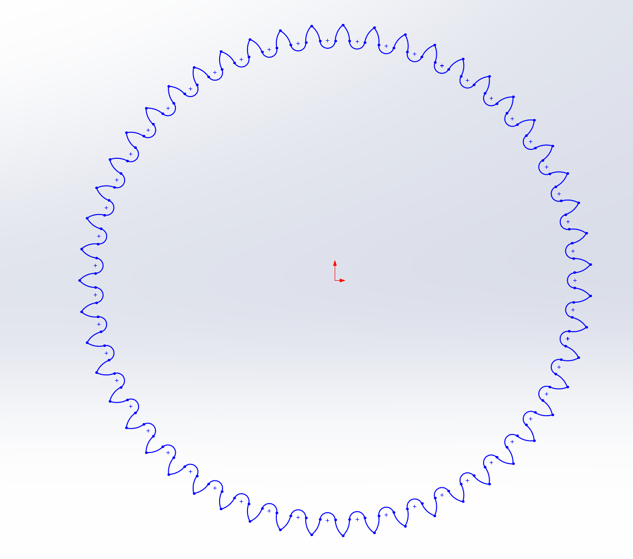
Ok, here’s a picture of the cog as I modeled it last week and exported to DXF. This is a purely 2D drawing.
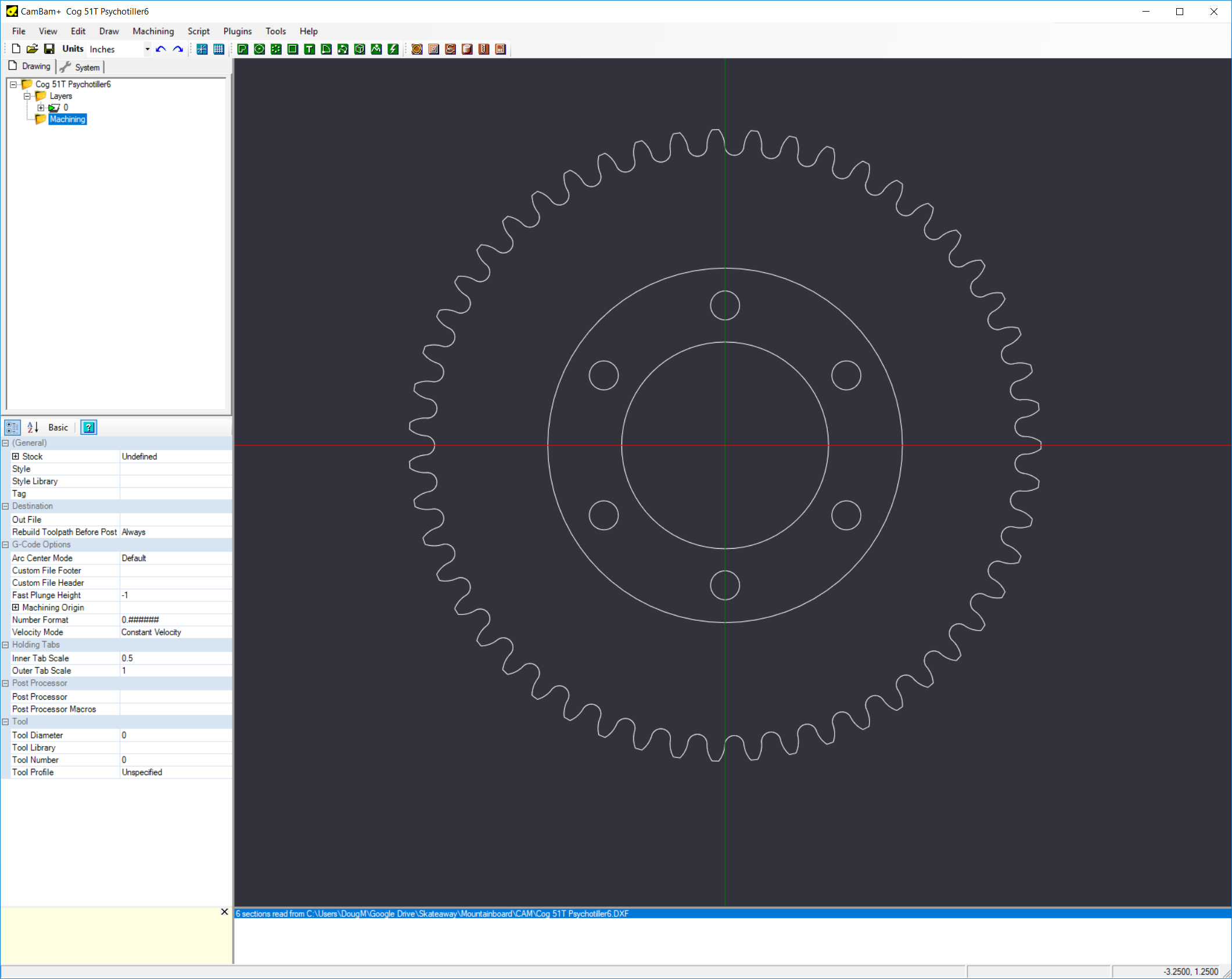
Every single one of those teeth is comprised of about 5 polylines, so you want to join them all together to make one big polyline:
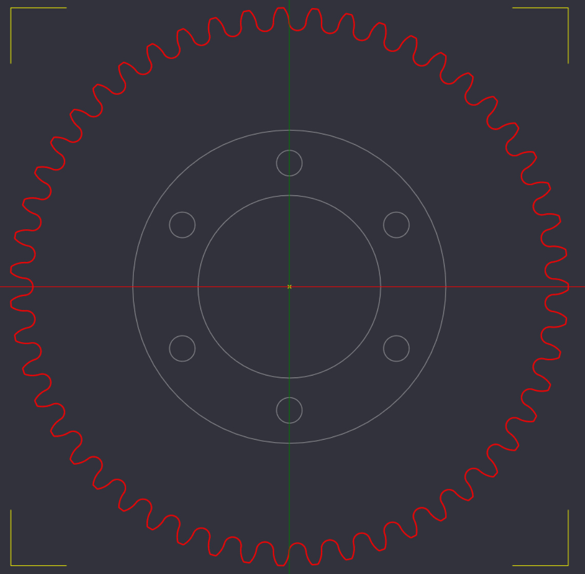
So now all I have to deal with is 6 screw holes, 1 big hole in the center, and the teeth. The rest I’ll do on the lathe by hand.
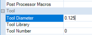
Set Machining Origin: This is where the mill will consider X=0; Y=0. I always use the lower left corner. In the image below the little red X is my machining origin. When I put the material in the mill I just move the cutter to the lower left corner of the material and home all axis’ Z is a bit different but we’ll get into that.

Next, set your tool diameter.
Next, I’m going to want the machine to separate the part from the surrounding material, so I need to add a cutout circle slightly larger than the teeth.

Ok, first drill some holes. This little menu thingie here is all the milling operations I can do. Number 5 is drill.

Basically now I just select the object I want to act on and apply the magic numbers we talked about above.
 _the green line is the circle we’re working on, the blue line is the tool path.
_
_the green line is the circle we’re working on, the blue line is the tool path.
_

Note the target depth. Remember that the Delrin I bought is 3/8" (0.375) so I add another little bit to make sure I cut all the way through the material. I have a plastic sheet underneath so I don’t cut into my milling table.
Repeat for all the rest of the holes:
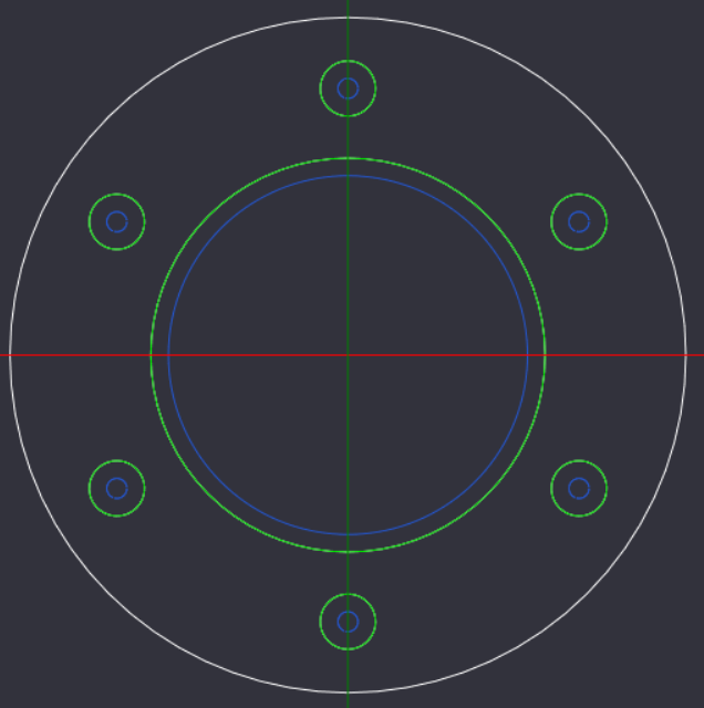
Now for the teeth I’m going to use a machining operation called a Profile (number 1 on the menu thingie). But it’s exactly the same as the drill, except that I’m not going all the way down since the teeth only have to be 0.120 wide I’m going to go to -0.200 and clean it up on the lathe.
 _red is the teeth, green is the tool path
Now do exactly the same thing for the cutout, except go to full depth. But wait! On your cutout you need to add some holding tabs so the work won’t try to run away.
 this shows the whole thing - all tool paths, holding tabs, etc.
Installment 3 is where I actually cut the thing on the mill, which might happen tomorrow, but don’t hold your breath.
_
5 Likes
Nice explanation.
Havent had a chance to do such cnc work so far but im happy u have given an insight about some of the details related to it.
I touched the topic about flexboardz design a while ago but to make one happen, I guess a decent machine shop is needed. So im glad u are heading in this direction.
Aaaaaaaaaaaaaand we’re motorized.
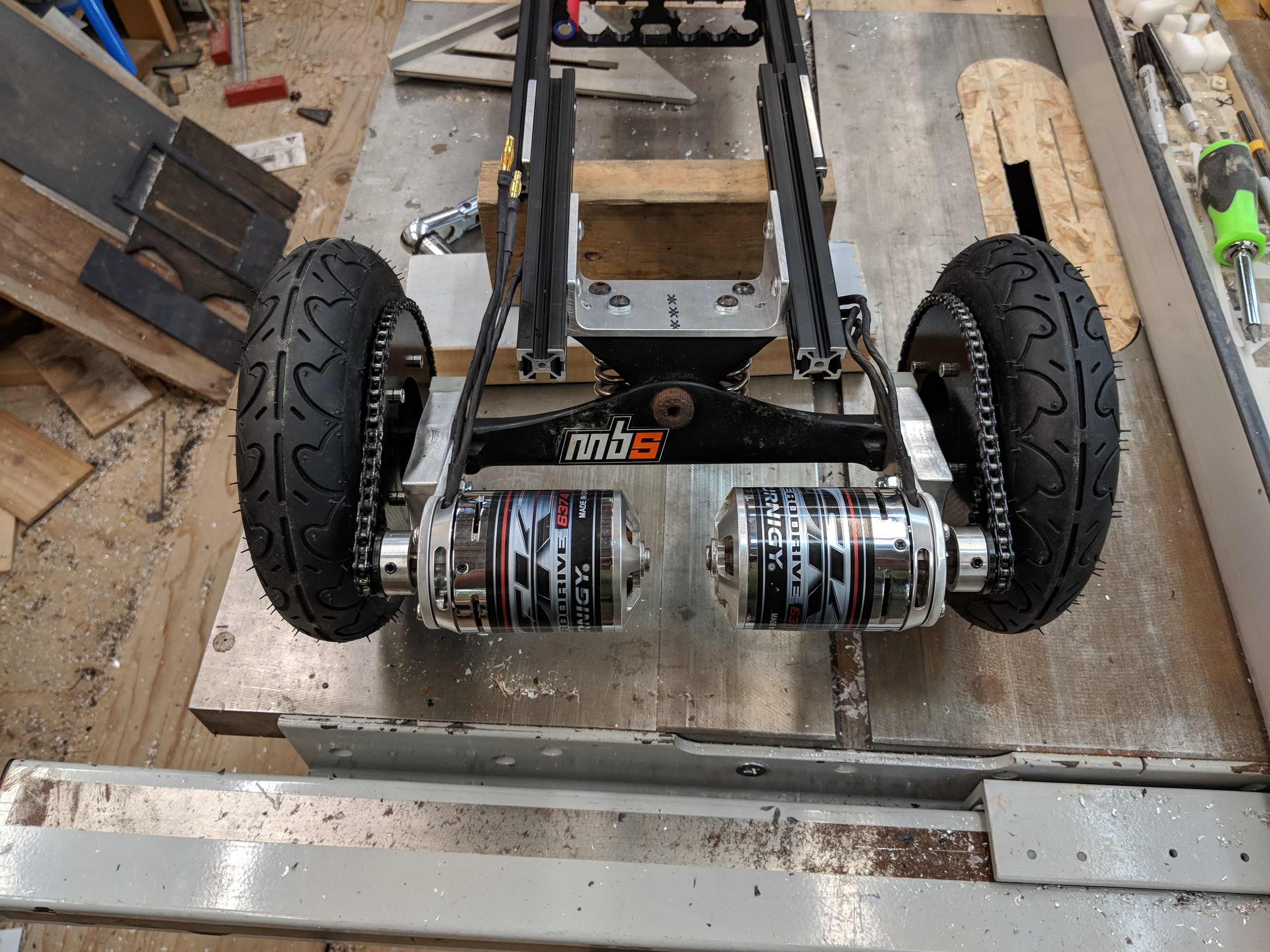
left on the list: mount deck think about waterproofity Mount VESC’s (4.12’s until the FOCBOX Unity is available) get more batteries weld up battery packs wire everything together add charge port charge ride
I’m a little lacking in torsional rigidity - need to give that some thought.
3 Likes