Hey there,
right now i am quite stuck… I have some broken vedder switches which i want to repair.
Now a little bit of story:
One time a broken switch just revived by vibration… the board with everything equipped was dropped from 20cm height. after the fall the switch just started working again… duno why…
Another switch did not power on at all. After some unplugging, changing the position of the softswitch and reconnecting it the esc got power. Then i have turned it off and it powered down. Since then the switch was working again.
Then i tried to revive another switch with the same method but it did not work at all.
Does anybody have an idea what could be the problem? Would be great if you @chaka could chime in here because i think you have the best knowledge about these switches but everyone is welcome to help.
Yes, i have measured everything like you said. Here are the results of my three broken switches but i think i only need help for the first two because the third one just seems to need a new zener diode.
When the SPDT switch is turned one way there are two leads connected. The connected leads have been marked with an “X”. The measured voltage is of each individuell pad in the “X”-marked stage. Therefore i have made two pictures for one switch. For each of the two positions of the soft switch
I have measured the voltage like you have shown in red. The resistance is fine too…
When the SPDT switch is turned one way there are two leads connected. The connected leads have been marked with an “X”. The measured voltage is of each individuell pad in the “X”-marked stage. Therefore i have made two pictures for one switch. For each of the two positions of the soft switch I hope that clears things up.


 .
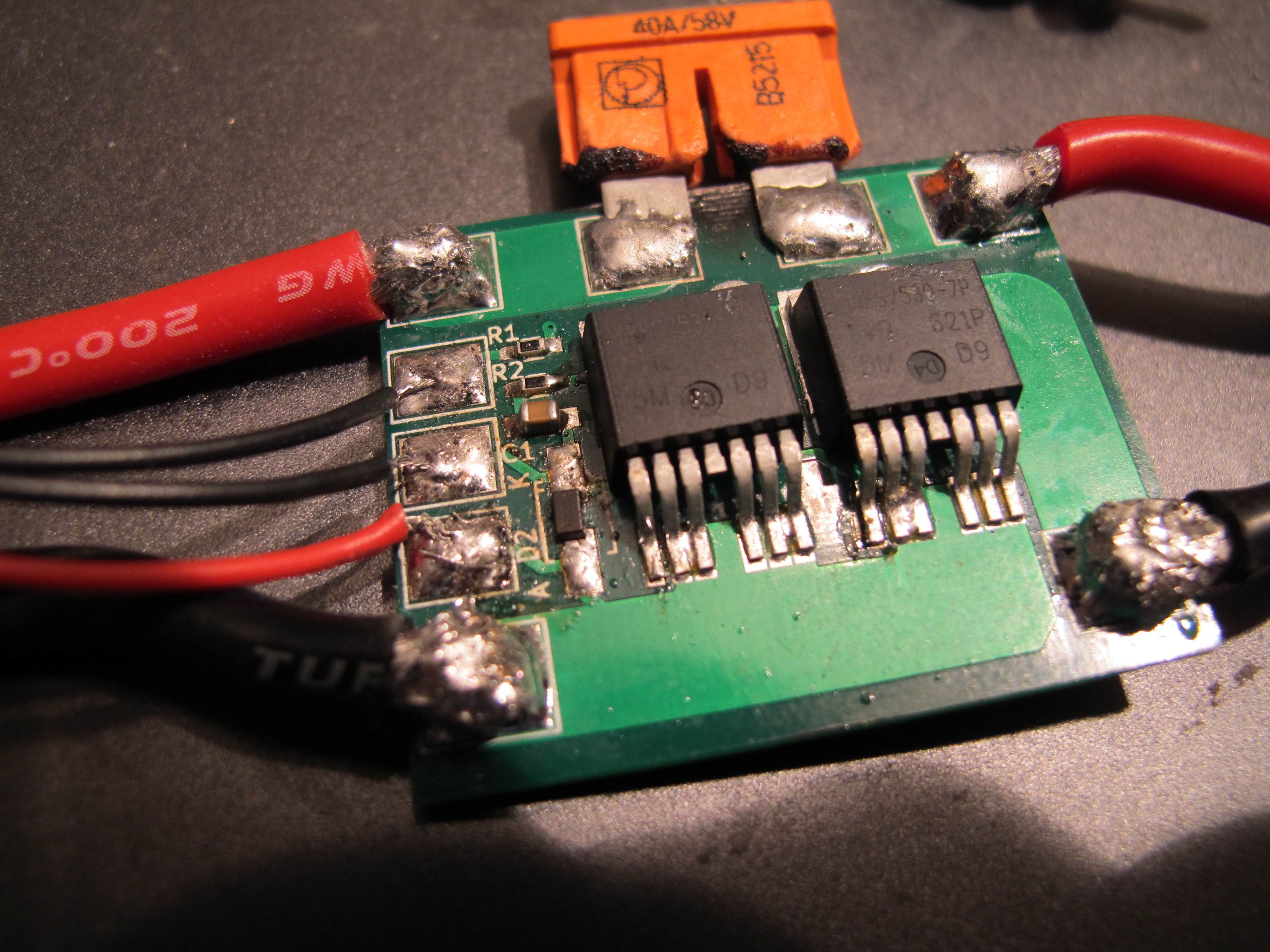
Do you used a hot air station to solder the FETs?
.
Do you used a hot air station to solder the FETs? But you are right, it looks awfully