Hello All,
I’m here to bring forward some simulation data on the available hub motors. These simulations assume that the VESC is a Sinusoidal, Space Vector Modulation @ 6 Khz or 20Khz. I am going to present the information available for @Hummie and @jacobbloy’s hub motor designs. Because of the limitations of the software I am using, I cannot simulate their temperatures. That said, the temperatures I do simulate do not account for passive air cooling through vents or shaft/hangar heat sinks (@carl.1).
Target RMS Current is 30Amps for these simulations. I do account for the voltage difference between Jacobs (10s) and Hummie’s (12s). I ask that everyone STOP TALKING ABOUT KV. Focus on Temperature and Torque because those are the variables we need to be more careful about - not speed! Scaling can happen later. If you can respect that, then please add your commentary.
I’ll update this as I get around to it. If people want me to produce more accurate results, I do not have any version of Hummie’s motors so please tell me the specs.
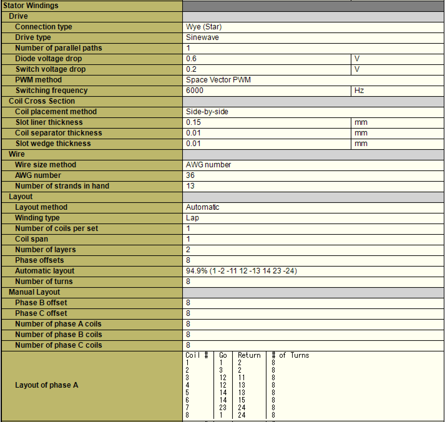
Jacob’s V2 Motors (24 Pole, Wye)
6Khz SVM Freq.
20Khz SVM Freq.

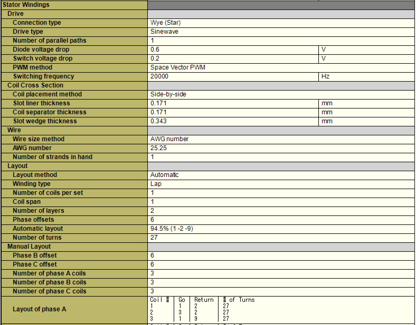
Winding Specs.

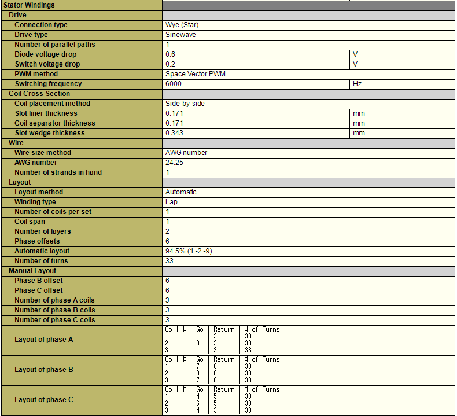
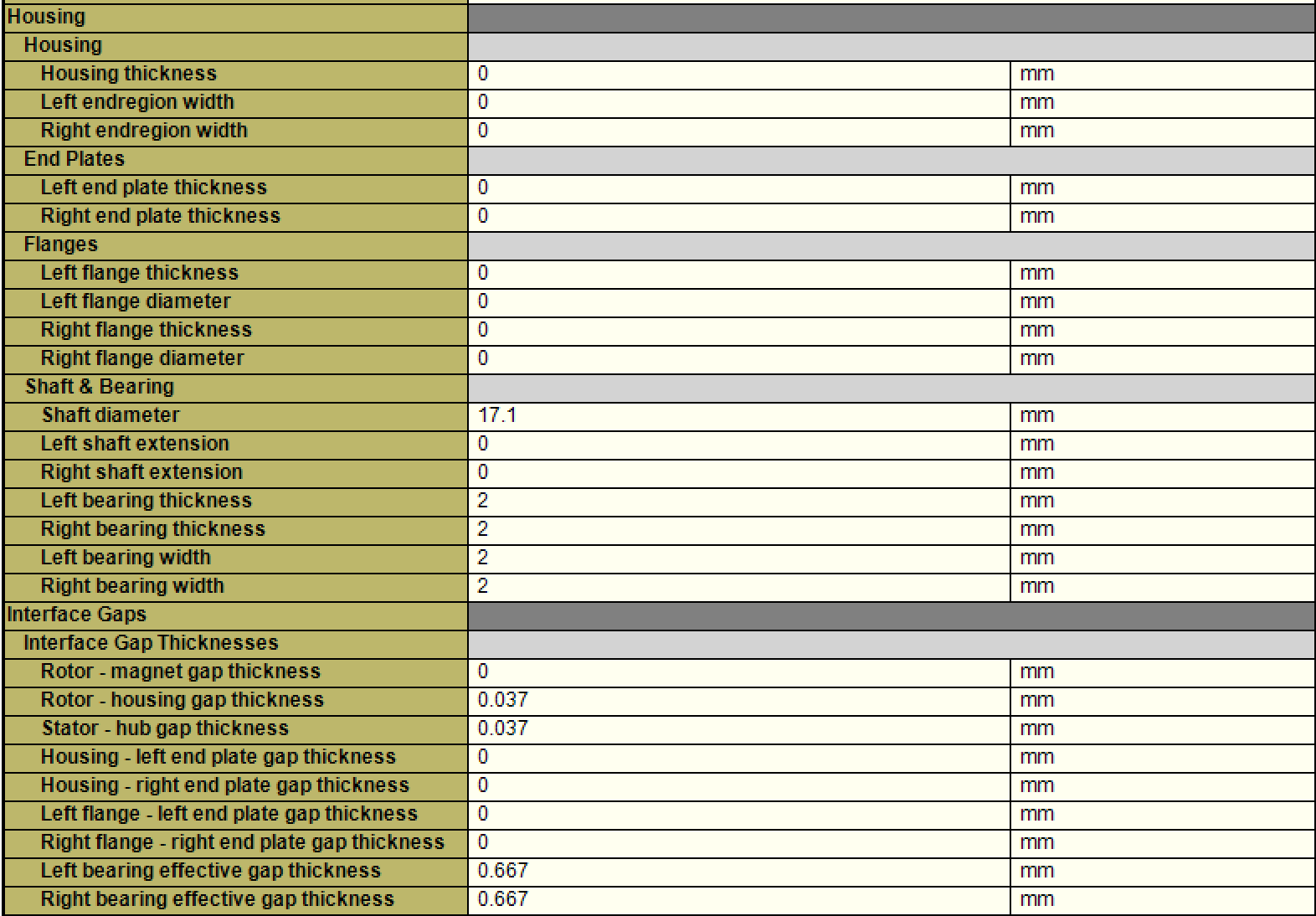
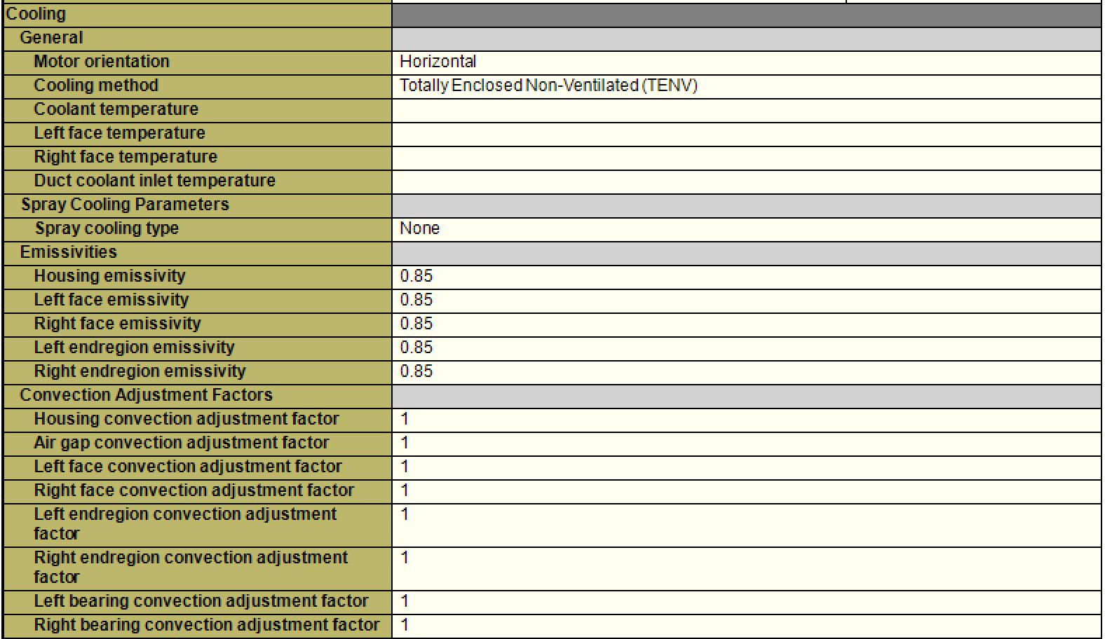
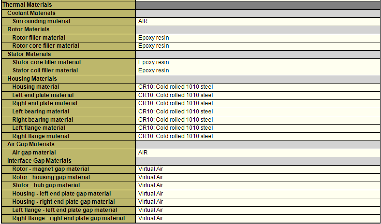
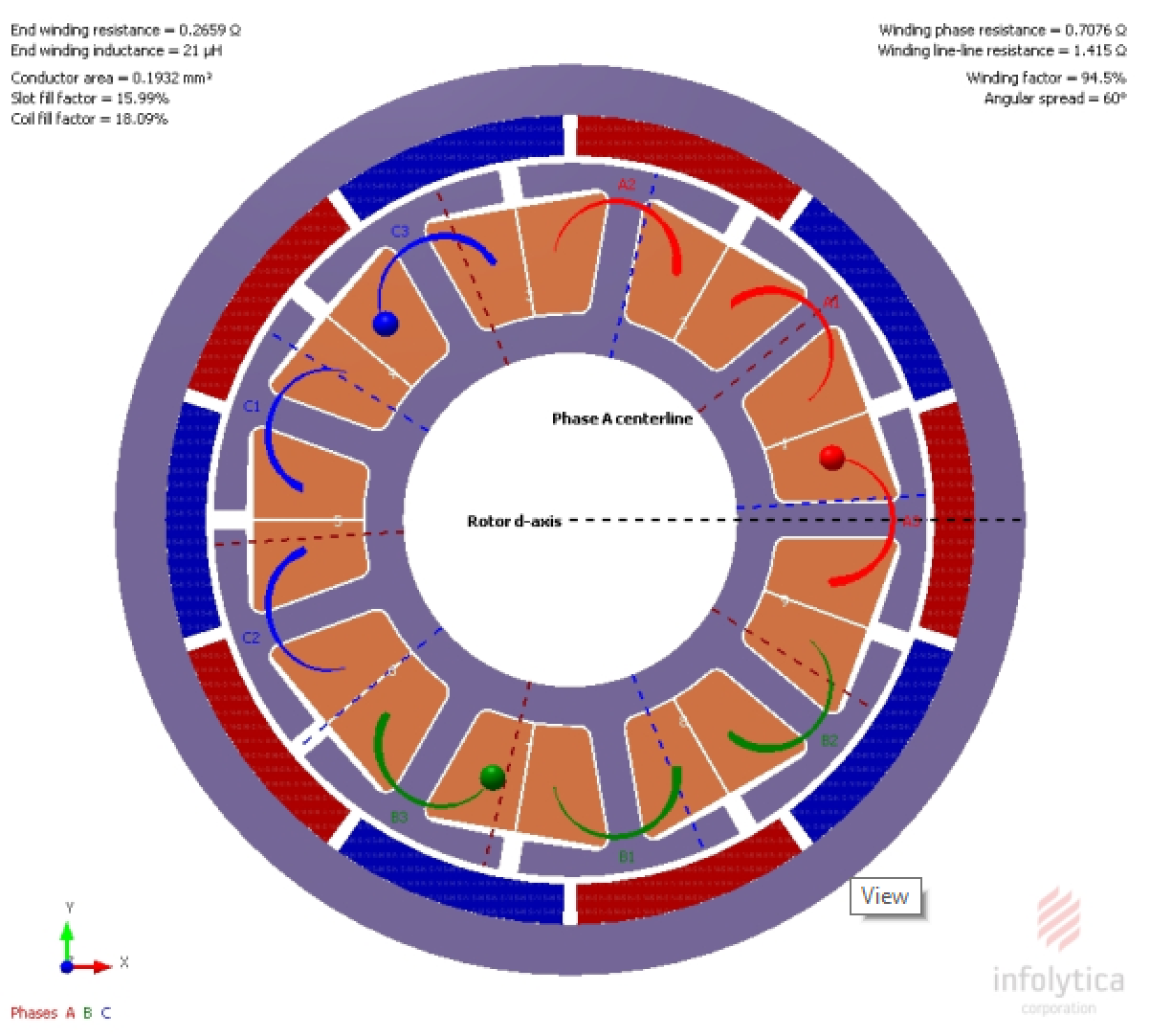
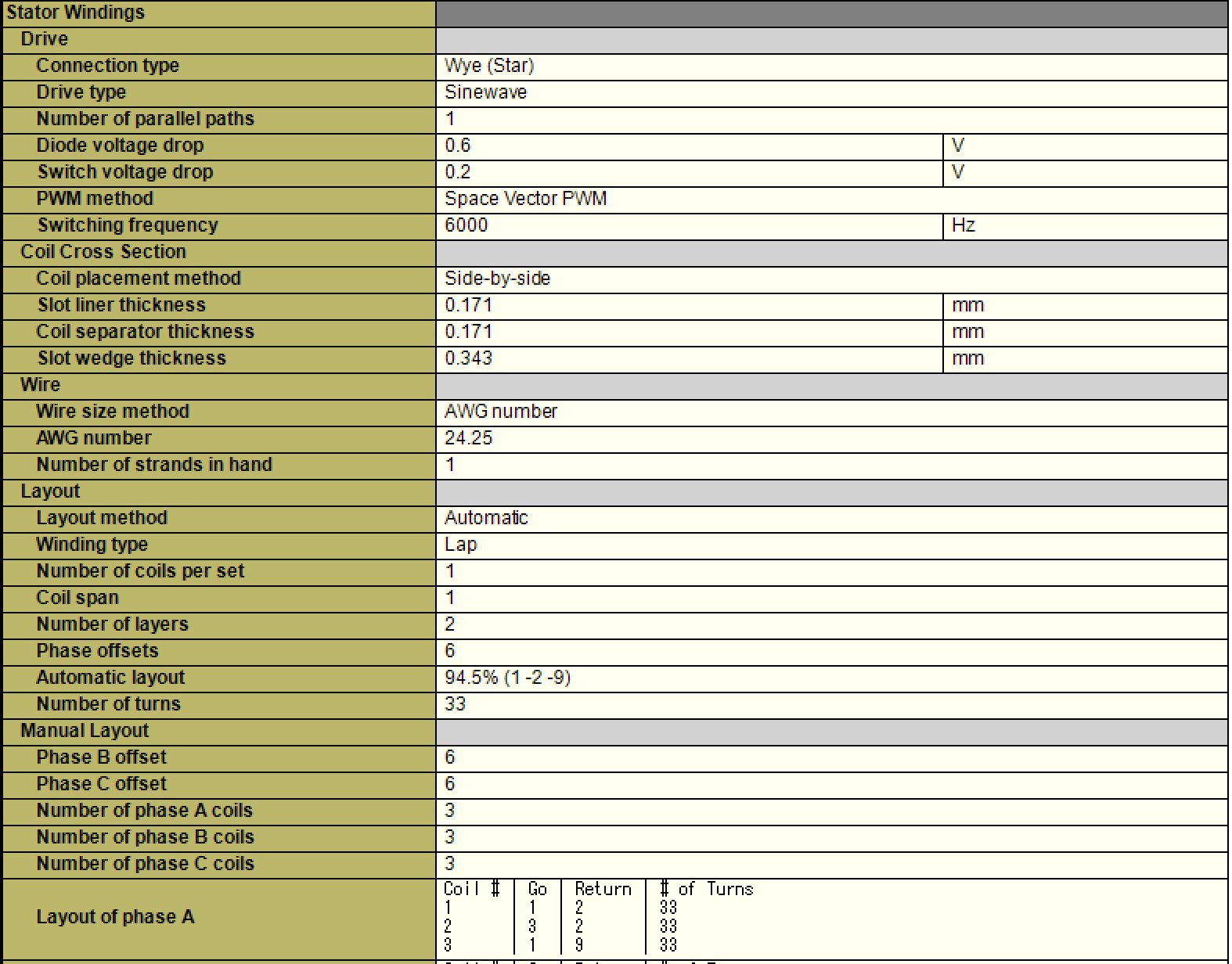
Hummie’s V2 Motors (12 Pole, Wye???, 80 kv)
I interpert this to mean that his 80 kv model is 24.25 Awg, 1 Strand, 33 Turns.
6Khz SVM Freq.

20Khz SVM Freq.

Winding Specs.
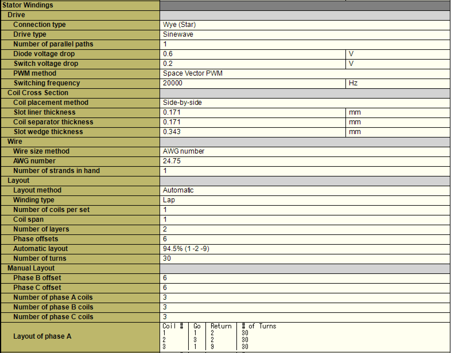
Hummie’s V2 Motors (12 Pole, Wye???, 90 kv)
I interpert this to mean that his 90 kv model is 24.75 Awg, 1 Strand, 30 Turns.
6Khz SVM Freq.

20Khz SVM Freq.

Winding Specs.

Hummie’s V2 Motors (12 Pole, Wye???, 100 kv)
I interpert this to mean that his 100 kv model is Awg, 1 Strand, 27 Turns.
6Khz SVM Freq.

20Khz SVM Freq.

Winding Specs.

Reference:
VESC: Sinusiosal SVM 20,000hz switching
Torque for 80mm Wheel to stall/equal to gravity with a 100kg load: 05% - 3.9Nm total (or 3.9/2 Nm per motor) 10% - 7.8Nm total 15% - 12Nm total 20% - 15Nm total 25% - 19Nm total
RPM/Speed for 80mm Wheel: 0560 - 05 mph / 8.1 kmh 1100 - 10 mph / 16 kmh 1600 - 15 mph / 24 kmh 2100 - 20 mph / 32 kmh 2700 - 25 mph / 40 kmh
For the same max current, Jacob’s Hubs are superior. That does not mean that they are without fault. The losses are significantly lower however. -KM