So I received both my HobbyKing GT2B and my @MasterCho mod/case which was purchased from @JLabs (The enclosure not the remote). The mod/case looks great and feels great, it fits all the necessary components. The problem I am having occurred after I modded the battery according to the Endless Sphere Badwolf GT2B mod which you can see here https://endless-sphere.com/forums/viewtopic.php?f=35&t=71922.I took the battery apart and soldered on the connector that was originally from the channel three button to the main board (PCB?). I removed the white wire as I don’t need channel three, and soldered the red to positive and black to negative as fast as I could as to not heat up the battery. I managed to do it pretty quickly on the positive side, but the negative side I had to heat up a number of times though very quickly each time (maybe 5 time total?). I really hope I haven’t damaged the battery beyond repair. Now when I plug it in to charge there is a red light, though no matter how long I let it sit for, it doesn’t turn green to indicate a full charge. When I move the power switch to the on position while it is charging, the charging LED turns green. No matter what though, I can’t get the lights that indicate that the remote is on to turn on. When the charging cable is plugged in WITHOUT the battery, the charging LED is always green no matter what position the switch is in. This to me indicates that the battery is at least somewhat hooked up to the system. I also know that the main power switch is working because it changes the color from red to green when the battery is plugged in and charging (as mentioned before) so that can’t be the problem. This has been a really long post and I apologize but I am just bummed that it isn’t working because I don’t know what I did. I have included many pictures and the angles aren’t great since they were taken on a laptop. Thanks and hope you can help!
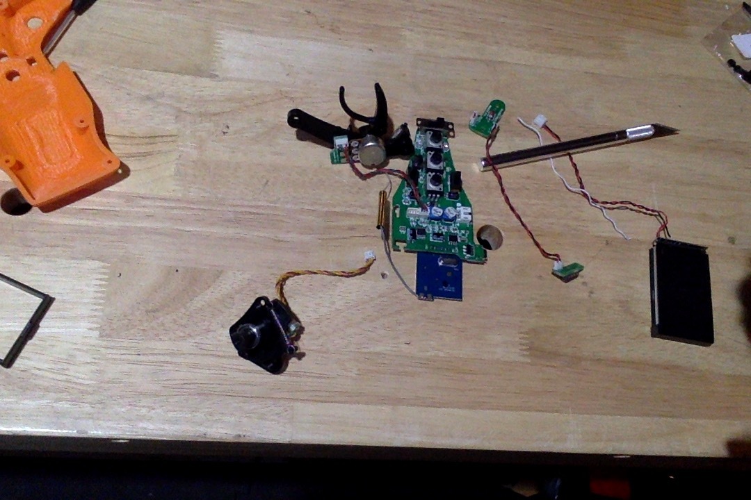
The whole system
The battery from the top
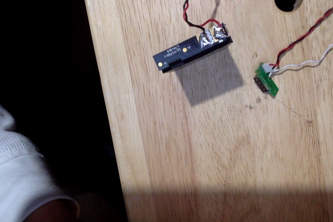
The connector that was originally from the channel three button to the PCB. I am showing how I cut off the white wire.

This is to show that the metal strips coming from the battery are intact

Another close up of the connections to show that they are solid

In this picture, the switch is in the OFF position

In this one the switch is in the ON position and as you can see, no LED

In this one, it is charging with the switch in the OFF position and there is a red LED

Finally, this one is charging with the switch in the ON position, and there is a green LED

For the few of you who read this post all the way through thank you a ton, and I really hope you guys can help me out.


 if it comes off easily, and check the voltage.