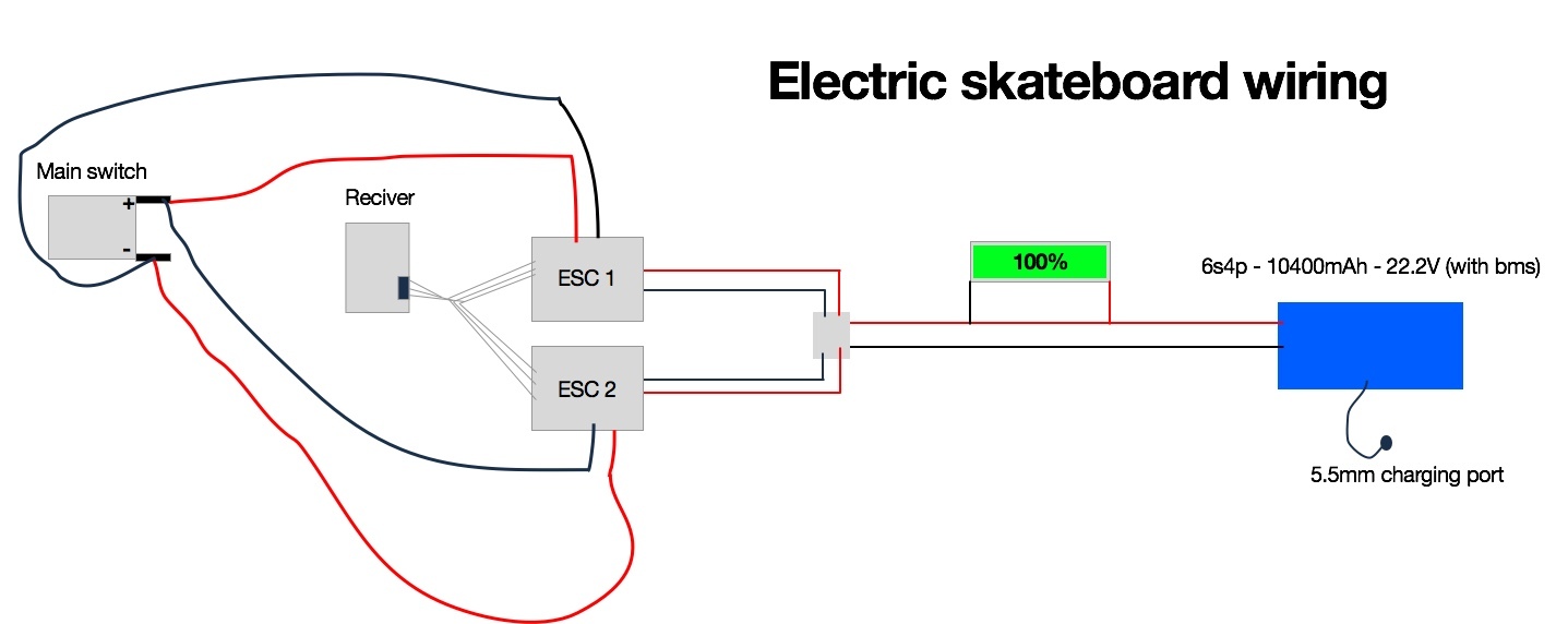
Hi, im going to build my first electric longboard and I am a little bit unsure if this wiring would actually work.
I would like to have the battery on one end and the other electronics by the motors, and have flat braided cables under the grip tape to connect it. Is it possible to have the battery connected to the ecs’s constantly and switch the board on/off with the ecs switches?
If you see something crazy please let me know. Also, I would like to remove the two switches that come with the esc’s and instead wire a normal 12v switch instead that turn both esc’s on. I drew all the switches just so you guys can see what I mean.
Hey man, pretty sure the main switch doesn’t turn the board off. as long as either the main switch or one of the side switches is on, the esc will get power. instead, you need to wire the main switch so that for for both switches, the main switch is is series.
Your battery indicator will be turned on the entire time and drain your battery. Better to connect its ground to the switch as well. Also it will simply not work like this and I am pretty sure you meant to connect the voltmeter ground to the actual battery ground in your drawing.
Like this (excuse my poor laptop drawing skills). The idea here is that when the main switch is off, the wiring is disconnected fully. @Maxid, as lon as there’s no conection from the positive end to the negative end when the switch is off, the battery indicator won’t be powered.
Also, another thing which we didn’t mention was that you had both positive and negatives going to the switch the wrong way. thay would always have the circuit complete which would explode your battery.
Sorry, didn’t see that part. With the stuff you have listed, it would be impossible no matter which way you wire it. You would need to use something called a relay to have a lower voltage switch control a higher voltage. The relay itself would need power and is honestly not worth it here.
Why not just repurpose the esc switch as the main switch?
If the main switch is off, there’s nothing wrong with leaving it connected. there’s nothing wrong with leaving it charging while connected; since I don’t know what kind of battery it is, I can’t confirm it’s okay to have the system on while charging, but you can do a poor man’s test by checking to make sure the battery doesn’t get too hot.
@Johan, don’t take this personally, but a question like that is something that you can just google without asking others since the question is just factual/technical. Here’s a link to a website that answers your question.
Also why are you going for a complicated high current switch when the esc ones can easily be switched with a low current one. I will try to draw something tomorrow.
Dude please stop giving electrical advice if you do not know what you are talking about - this can be really dangerous.
It is not just the voltage but also the current that is the problem. Voltage does not go “through” anything - current does.
what brand and model of Esc’s are you planning to use. Some cannot be connected to one switch but must have their own separate switches. And you should put the main switch at the battery to switch it off and on. Anyway, not all RC car Esc’s are good for this application.
Also, if your planning to run dual motors, then you should consider running higher voltage system.
Here’s a better diagram of an appropriate way of doing what you want.
the circled “A” is an ammeter, the circled “V” is your battery gauge, the disconnec partt being the switch, the box a fuse, the battery the double horrizontal bars, and the esc pretty self explanatory,