this is my first project like this and although i have read a LOT about this topic (thanks for all the details in your amazing builds btw.) I still have some questions. I am planing on a single motor build
-SK3 6364 190KV,
-3D printed motor mount with printed gearing as well (15-36) 15mm belt
-90mm flywheel clones,
-10S4P Battery from 30Q cells
and a Vesc to keep everything in control. Now my first Question:
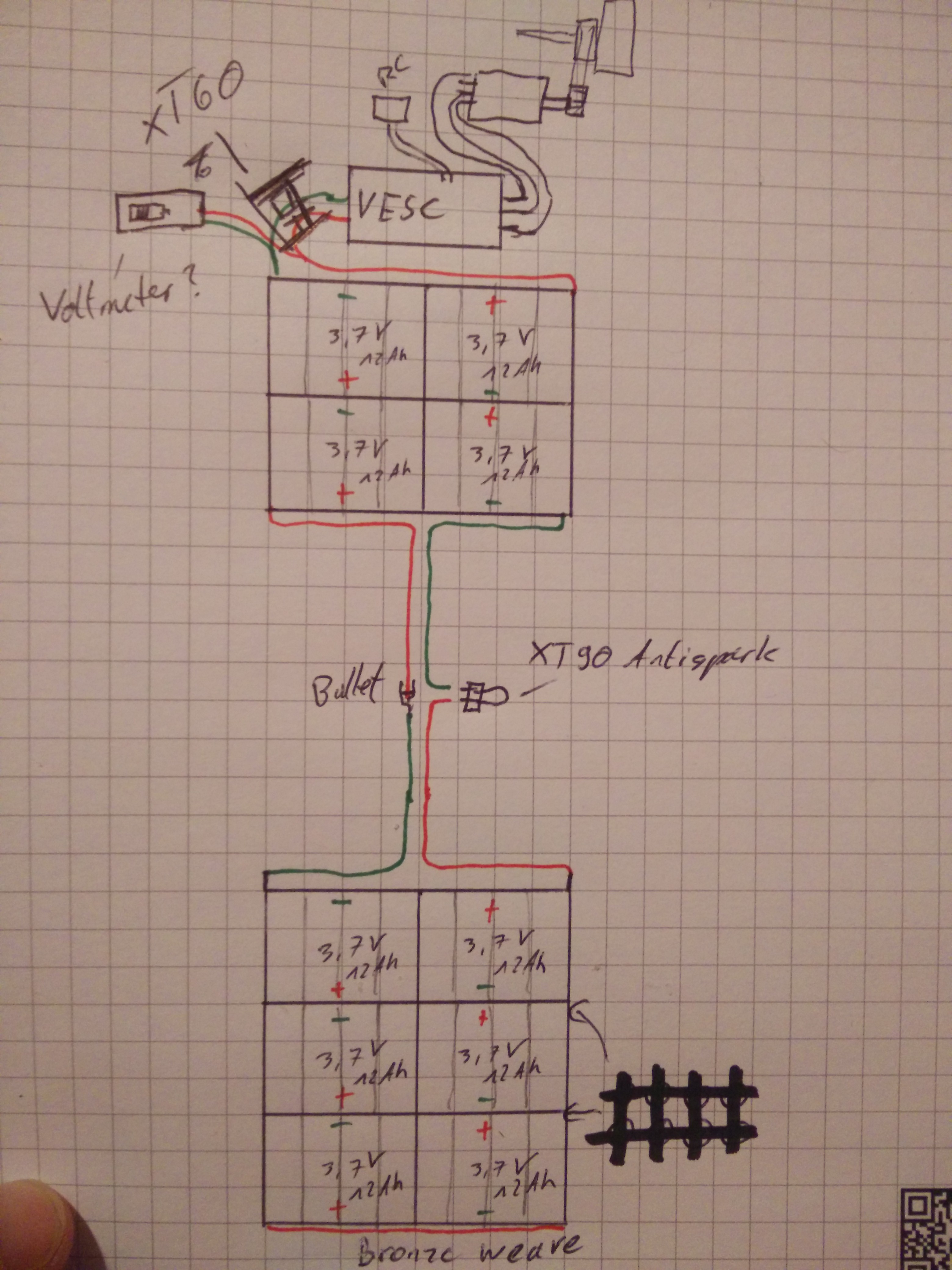
would it work like this:
I think the wiring is ok like this(?) but in about 90% of the builds i have seen on this forum the batteries are arranged crosswise, is there any advantage to that?
And which thickness of cable is recommendable for this kind of setup?
I’d love any input you can offer me,
Cheers and have a good night.
Looks pretty good to me, but maybe check with someone else just in case. I did a similar setup with a split battery and used 10AWG silicone wire. One thing to think about is including a balance/charge circuit.
I thought i would use the place where the anti spark plug is to charge the batteries? Or is this unwise because of sparks? Could I simply install a splitter the way I plan for the Voltmeter?
Concerning balance, I was just going check the packs every few month.
This would work fine with no BMS and never charging it. I don’t think you’ll be able to hook up a BMS and/or charge it unless you intend to charge it only with the loop key installed. And even then, I think the balace wires would present a big problem. I would move the loop key as others suggested
I don’t undestand why i would have to change the position of the loop key, sorry I don’t mean to question your judgement, I would just like to understand
If I installed a double XT60 switch at the top, could I charge the batteries through that? of course with the antispark plugged in!
Sorry for the hassle …
For the antispark to antispark it needs to between the vesc and battery, otherwise you’ll get current inrush as soon as you plug in xt90s in the middle of the pack, it needs be at the start
It will not perform antispark function otherwise, it’ll just be a connector
Should put the antispark between the battery and the vesc and the volt meter between the antispark and the vesc, 3d printed motor mount might break tho
The antispark just works by temporarily adding a resistor into the circuit before the loopkey is fully inserted which prevents the sudden rush of current when the loopkey first makes contact with the rest of the circuit.
Fairly sure that it shouldn’t make a difference where in the circuit the resistor goes as long as it creates a point in the circuit that limits the current
This is a good point, not sure how much luck others have had with 3D printing these sorts of parts but I personally wouldn’t trust a 3D printed motor mount long term. Will depend a lot on the material you’re using though
 about this topic (thanks for all the details in your amazing builds btw.) I still have some questions. I am planing on a single motor build
-SK3 6364 190KV,
about this topic (thanks for all the details in your amazing builds btw.) I still have some questions. I am planing on a single motor build
-SK3 6364 190KV,