Hi all,
I started this build in early June and I’m still on it. It takes time because I’m keeping changing ideas about what I finally want.
So let’s go for a quick presentation then I’ll try to retrace the history of the build.
Specs :
- Deck : WeFunk DH38
- Trucks : Caliber II 50° + pads 6mm
- Wheels : ABEC11 Flywheels 83mm 80A
- Bearings : Amphetamine Ceramix silver + speed rings
- Motor mount : DIY ES v4
- Tranmission : 15x36 width 15mm
- Motor : APS 6355 190KV sensored
- Batteries : Flightmax 2x 5S 8000mAh
- BMS : APS BMS 10S + charger
- ESC : DIY ES VESC 4.12
- Enclosure : home made
- Powerswitch : Vedder Powerswitch (esk8.de)
- Remote : GT2B + 3D printed enclosure
- Others : Arduino + LCD2x16 + temperature sensors + switch with led ring, headlight and rearlight
Features :
- Top speed : 40km/h
- Range : more or less 20km
- Charge smartphones
- Bluetooth music speakers embedded
- LCD screen embedded with tons of infos
- Headlight and rearlight controlled by the remote
Building the board :
“Christmas everyday” time


Starting prototyping, making and coding my home made electronic board :
At this point, I wanted to communicate with the VESC though UART, display datas on the LCD, datalog on a microSD card. and control the lights. The board shall also be a hub to supply power to electronic devices (USB plugs, BT speakers…). Power supply : UBEC 5A + 2A channel switched by RC receiver using CH3 button of the GT2B.

After many hours of coding and modifying the existing Rollinggecko’s library (in order to include temperature and fault code management), I finally got a working version of my system. Almost working I should say, because I was unable to use LCD and microSD board working simultaneously…

Then I switched to a brand new stuff for me : create the enclosure ! It was not so difficult finally and I’m pretty happy with the result.


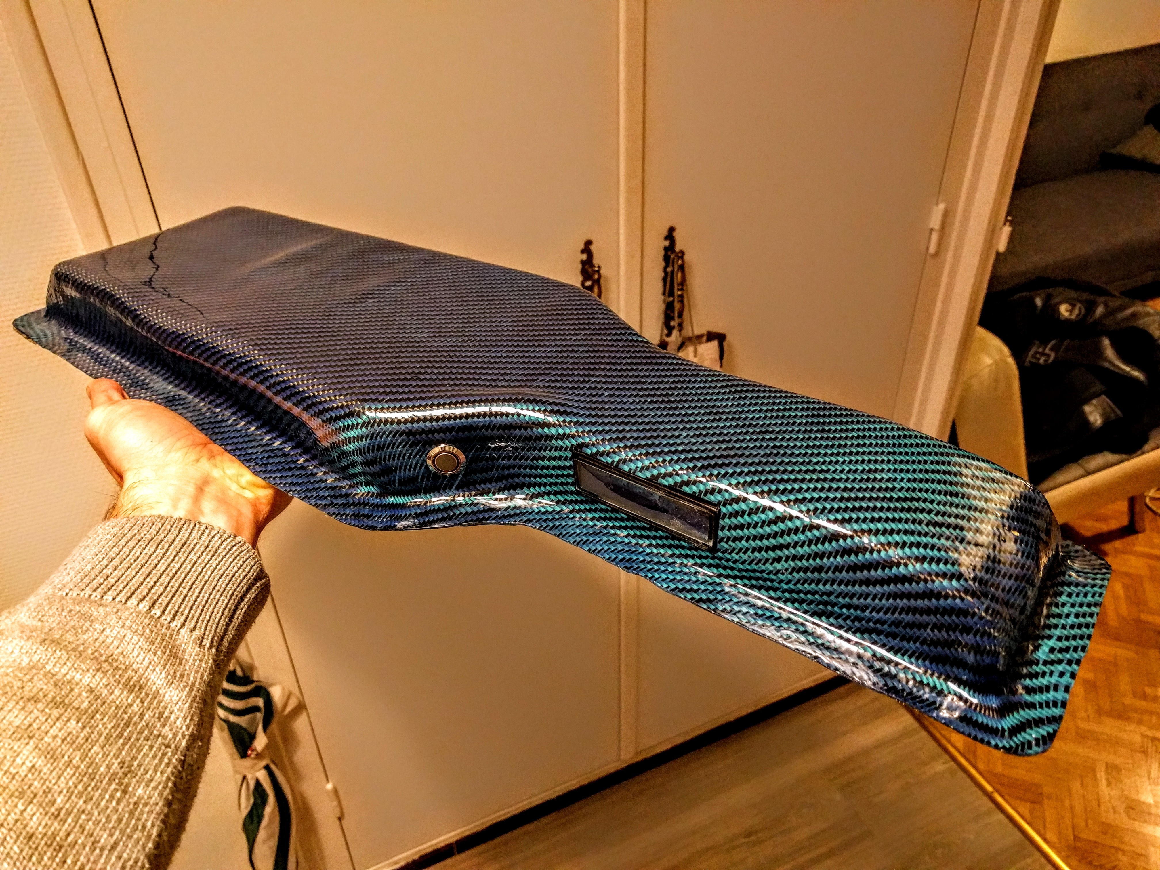
I found with carbon fiber with blue polyester fiber cloth very beautiful ! So I decided to cover the bottom of the board with it.
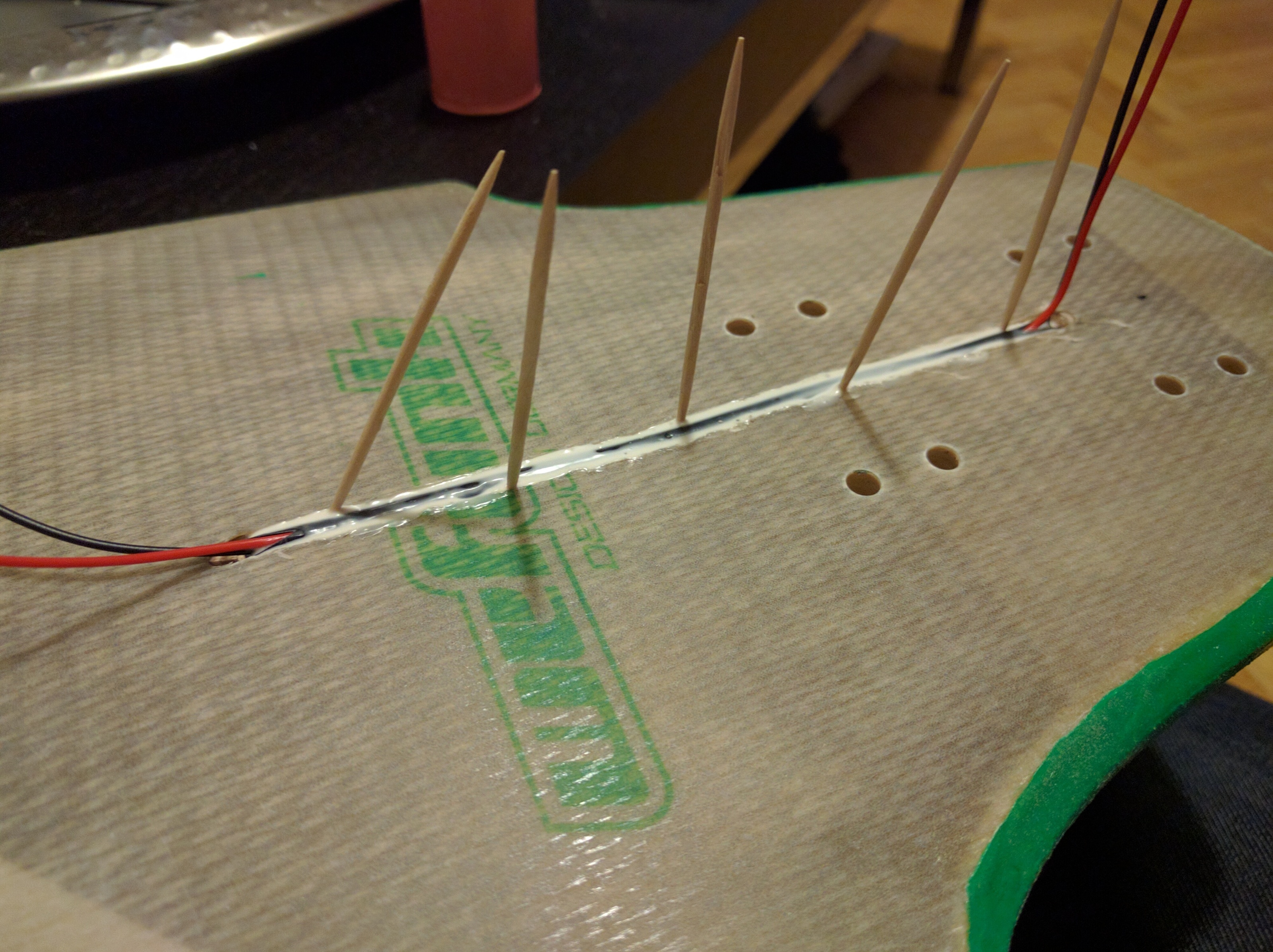
But before, I painted the edge with the ABEC11 flywheels green color and route the board for the lights wires. Because the wires are thin, I could put them into a “duct” (actually a bad quality shrink tube I didn’t heat) to be able to remove/add/change a wire if needed.


After sanding and preparing the routes, time was come to cover the whole board. Not whole in fact, I wanted to keep clear the hidden surface to avoid blocking RF receiver with a total carbon fiber enclosure.


Well, it’s not Whitepony’s quality but anyway… For a first try, it’s quite enough for me ! ![]() And with a epoxy resin layer on it (edge included), if you don’t look at it too close, it’s clean enough.
And with a epoxy resin layer on it (edge included), if you don’t look at it too close, it’s clean enough.

That being made, I came back to electronics and build the Mad munkey remote form @FLATLINEcustoms . Amazing mod after all !

While the 3D printer was still hot, I printed headlight and rearlight enclosure (from scratch).


I published the headlight print on Thingiverse if you’re interested in : Longboard led headlight by Peemouse - Thingiverse I still have a little change to add and it will be in release status.
I kept Solidworks open and designed/printed the plug panel (for USB plugs, BMS charger and BT speaker commands)
http://img15.hostingpics.net/pics/987860panelboardv11back.png (I don’t have pictures of the real part, sorry)
At this point, I tested Bluetooth modules (HC05) and played a bit with VESC Monitor. I fell in love with that !!! But I had to choose between my own Arduino system and BT because the VESC has only one UART port… I chose BT. So I threw my previous board away and started to build a new one with these small features :
- Measure battery voltage (with a voltage divider) and display it
- Measure temperature inside the enclosure
- Still support a hub connection with now 2 different supplies : main and switched for light control.

Time was come to put all these stuff on the board and screw the enclosure.
But I missed some point during the build and the enclosure was too small to fit with the implementation of the elements. Basically, the only way to close the box is to put the powerswitch above the BMS.

So I designed and printed a structure to make it possible without electrical and thermal issues. I had to modify it because the switches on the enclosure are hitting it… Here is what the build looks like presently :

Yesterday I decided to drill and set the insert for screwing the enclosure. I was still a bit “tired” of the party and didn’t make a good job…
I cut the headlight wires (I drilled in it, I forgot it was behind ![]() ), the powerswitch doesn’t want to switch off anymore and one of the LED of the rearlight is fried.
Time to sleep I guess.
), the powerswitch doesn’t want to switch off anymore and one of the LED of the rearlight is fried.
Time to sleep I guess. ![]()
To do :
- Replace the headlight wire
- Replace the powerswitch (the new one is on the road, thousand thanks to @elkick )
- Adjust components to close easily and safely the enclosure
- Some wire length adjustment
- RIDE, RIDE, RIDE and RIDE !!!


