Latching Relay Based Main Switch ( in lieu of electronic anti-spark switch)

Due to unreliability of anti-spark switches and having gone through two failing closed in past 12 months – I have built and tried a latching relay based alternative to use in a new build I am commencing.

I want the main power switch to be 100% reliable 100% of the time.

The new build will be a 10S system using dual vescs.

Basic design concept is to use • a heavy duty latching relay as main +ve power switching from battery +ve to vescs +ve ( no BMS) 
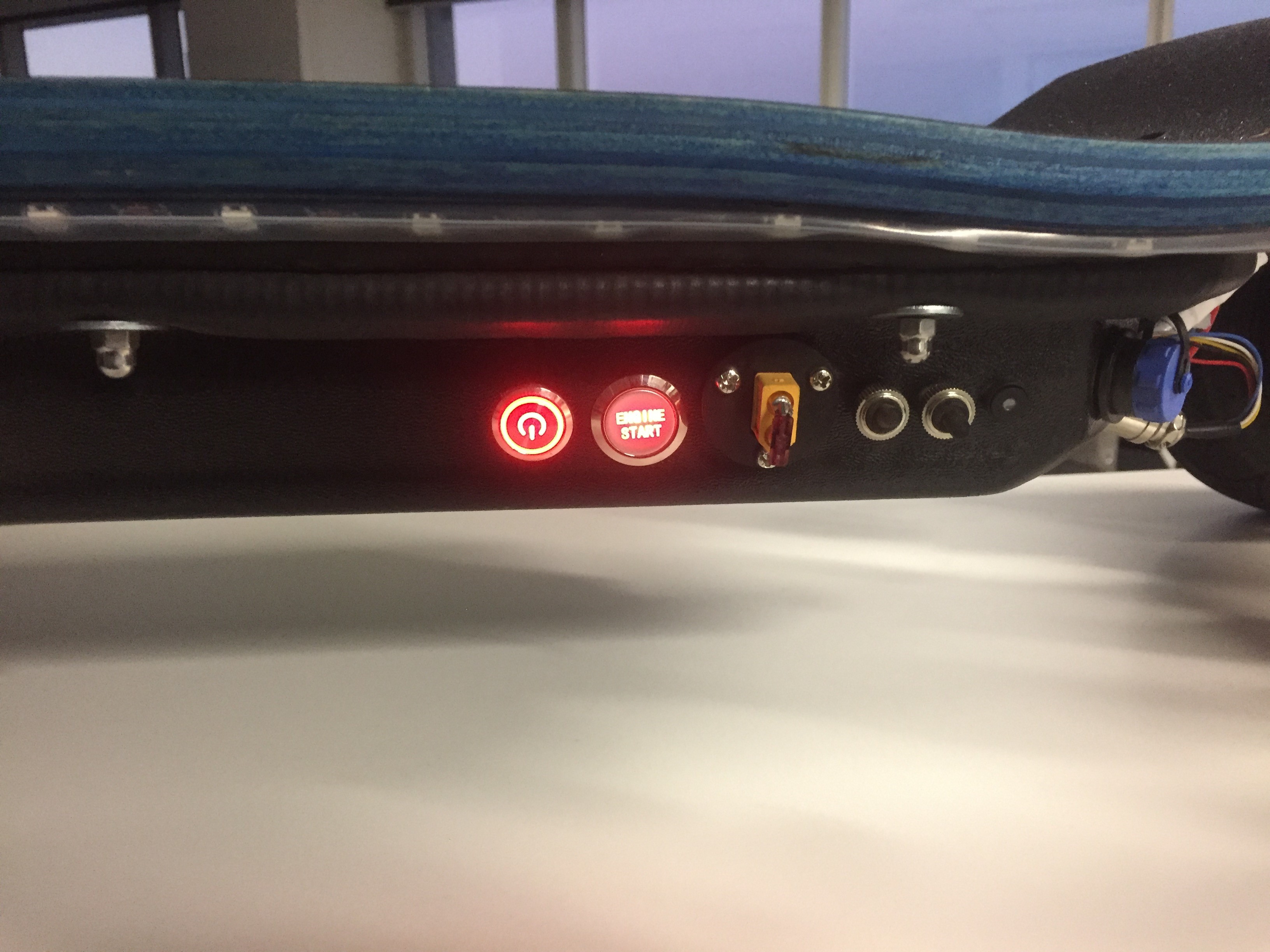
• two momentary action push-buttons – one for “close” and one for “open” with leds in push buttons to indicate latching relay status • no electronics (to fail from the transient voltage spikes!) • use main +42V supply rail to power relay switching circuits Started off looking around for a heavy duty latching relay. Settled on one from china link to latching relay . This unit is quite cheap (Approx. US$6). Ordered two and shipping was approx. 2 weeks. picture 1

This beast ticked most boxes. The contacts are rated at 80A at 240Vac with no dc rating indicated. The contacts are quite beefy and they should be OK for the application for battery through current whilst closed (My board draws about 40A maximum battery current).

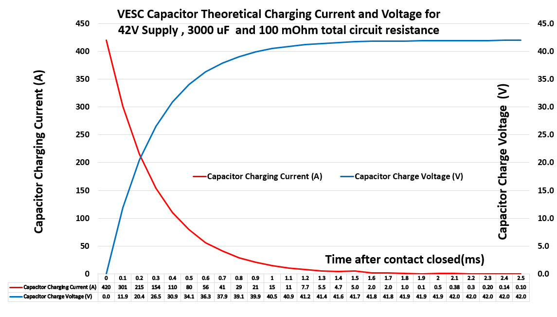
The relay dc breaking current will be practically zero (vescs idle current only)- the dc making current will be the vesc capacitor charging inrush current which causes the problems on electronic anti-spark switches.

As a test -I mocked the latching relay up through the XT90 main power socket on my existing board and completed 10 closes and opening onto dual vescs – took the cover off to look at the contacts and there was no visible signs at all of arcing on power contacts during both closing and opening.

This is probably due to the very positive mechanical action of contacts when making and the very low current when breaking. For the pushbuttons – using this one for “close” (it has a led built in)

picture 2
And this one for “open” picture 3

Any momentary illuminated pushbutton with spdt contacts will do the job.

The latching relay has a single 12V coil and you need to reverse current direction in the coil to reverse the latched main power contact operation.

This means a bit of control circuitry to achieve this. I used two mini 24V relays (each with 2x SPDT contacts) hot-glued to back of latching relay. link to mini relay
picture 4 Reaching back approx. 20 years to my past EE days – designed up a hard-wired relay circuit with a bit of electrical interlocking between the two push-buttons to avoid shorting +42V control supply if both pushbuttons are operated.

circuit

Used a 2A wire fuse from input +v for control supply.

After testing – hot glued wires and connections to avoid any future issues from vibration. Bench tested OK and put aside for new build.

Total cost around $20 - around same size as anti-spark switch and hopefully a lot more reliable. latch relay 00latch relay 2latch relay 3latch relay 0latch relay 1latch relay 4

4 Likes

There is difference in between AC current and DC current… I doubt it even will hold 10A on DC level…

Thats how 50A DC relay looks like…

1 Like

For making and breaking 50A DC yes it needs to be like that -

but that is not the application here!

BTW no difference in thermal heating across power contact for AC or DC current

Are u for real boy? :joy:

1 Like

This isn’t true, but

My biggest concern is that heavy vibration will cause a mechanical system like this to fail. And that’s if you can stomach the weight and size and complexity issues.

1 Like

Hmmm… do you guys smell that???

I smell…

Bullshit

2 Likes

Yeah I love the idea then riding board, you loose brakes and etc for several seconds cause you hit a bump on the road :smiley: or VESC restarts and hits full throttle because some remotes fucks up on start up if you have some throttle :smiley:

Holy smokes! That seems convoluted!

This is all you need for a high current on/off switch…

Why the mean tone? Has this been tried/failed in the past already?

How many miles and what kind of juice have you had through that thing?

1 Like

IMO this is a bad idea. I’ve played with mechanical relays before and it’s no fun. You will pull crazy amps instantly on powerup, in order to charge the VESC capacitors. Even worse if you have additional caps. It will make a pretty large spark and wear those contacts out very fast, especially on a dual motor setup with twice the capacitors. (talking less than 100 switches)

You should look into latching solid state relays.

I’ve put hundreds of miles on my board with this switch… The battery is 8s4p LG HG2 so 80A constant.

There is an online voltage regulator bringing the voltage down to operate the coil with a rocker switch, one way ON other way OFF.

1 Like

Off topic: is that a benchwheel receiver?? I LOVE mine!!

1 Like

All I know about relays is from AvE… DC arcing is a concern when switching under load, right? And it’s breaking contact that’s more of a concern, not making? At least for function, not for wear/corrosion.

The things that skeeved me out is that it’s a AC relay not rated for DC function, and it’s a chinese relay that probably will perform way below spec. @SkaterBoy58 why not look for parts on digikey/mouser, with specs that have some meaning behind them?

VESC inrush current can exceed over 500A to charge caps :slight_smile: so you can expect freaking big sparks inside that relay switch…

1 Like

Yes. :wink:

It’s great!

Guys - The gross negativity and fearmongering from a forum seller of large expensive (almost same cost as a vesc) anti-spark switches when a much cheaper possibility is put forward is commercially understandable – but the personal attacks and vitriol in some of the above posts are not helpful to any-one.

This project is aimed at my new build which is pretty average – a 10S 8P battery, dual focboxes and dual 5065 1200W motors with 35A FLC.

So let’s have a closer look at the duty of a main switch between the battery and the dual focboxes.

There are three main duties through the latching relay contacts:

1. Continuous current whilst closed (thermal consideration only) On a normal ride I average about 10A battery current with a maximum of 40A battery current for high torque demand situations. Despite someone disagreeing with me above, 1A DC current gives same I^2R power loss as 1A (RMS) of AC current. So - averaged over a ride we are operating at an average of 10A for an 80A rated contact so the contact should be OK for this duty.

2. Breaking Current – this duty is to disconnect 42V supply power from vescs from an idle state. A pair of focboxes draw about 75mA idle current. This is a very easy breaking duty for the relay contact.

3. Making Current – the big one! This duty is to charge up vesc capacitors from 0V to 42V. This current is very high but for only a very short time. To demonstrate this – see below a theoretical graph showing current and voltage for close to what I have – I used 100m ohm as total system resistance. This includes battery internal resistance, wiring, relay contact resistance and capacitor bank internal resistance. The theoretical charging calculation is for scenario of 42V supply, 100 m ohm resistance charging a total of 3,000 uF capacitor bank. This combination has an RC time constant of 3 u seconds. (3/1,000,000 of a second) 2 x focboxes have about 2,800uF total capacitance on the input DC supply.

As can be seen from the theoretical graph, the current drops from maximum to almost 0 in just 3 ms (3/1000 of a second) and the large current (>15A) is over in just 1ms. If you do the calculation – the total cumulative energy for this making current duty is approx. 2.6 Joule or equivalent to 2.6 Watt second - so not huge.

I repeated this making duty test again 20 times using my 42V battery pack and dual focboxes – and there was no visible arc on making or evidence of relay contact burning. The latching relay has quite a large beefy contact and a very positive mechanical closing action.

In regarding vibration and the relay falling to bits – this will be tested in time as well. My enclosure has rubber strip seals to deck which does provide quite a bit of vibration dampening. Will mount the relay on side of enclosure on a foam pad as well.

Interesting that @darkkevind has been operating a similar latching relay with no issues – albeit with a different coil control circuit.

In regard to the negative comment above re relay weight and size – you can see it is about 35mm x 35mm and total weight is approx. 50g.

I will put this in my new build and will pull it out after 6 months service to see status of relay contacts and report back to this post. If it fails before hand - will also update this post.!

Cheers

6 Likes

Great post, thank you!

1 Like

Just to report back in : Latching Relay main switch in lieu of anti-spark switch has been in testing and service for a month now - no issues to date ! :smiley:

5 Likes

awesome looking but then i see what looks like an xt90 plug and there’s no way i’d get beyond just doing a loopkey there! like no other ive seen.