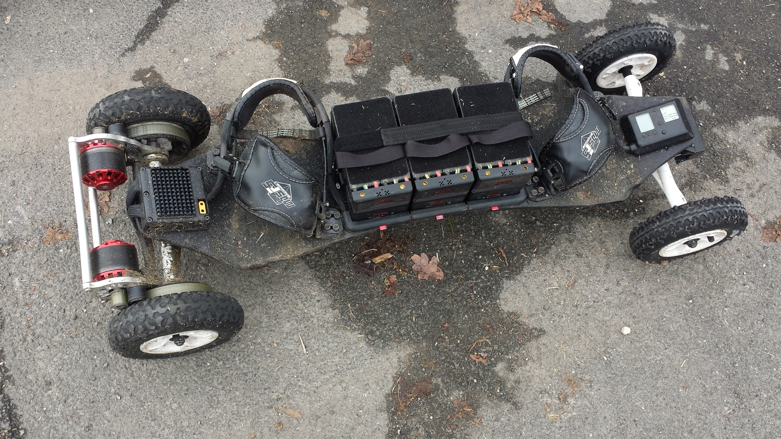
… it all started with a brand new MBS Core 94 mountainboard which weights only 5,9kg. Here in comparison to my big bad offroad board (buildthread coming soon…) which lets it look smaller than it is. It’s just about the same size as other Trampa builds.
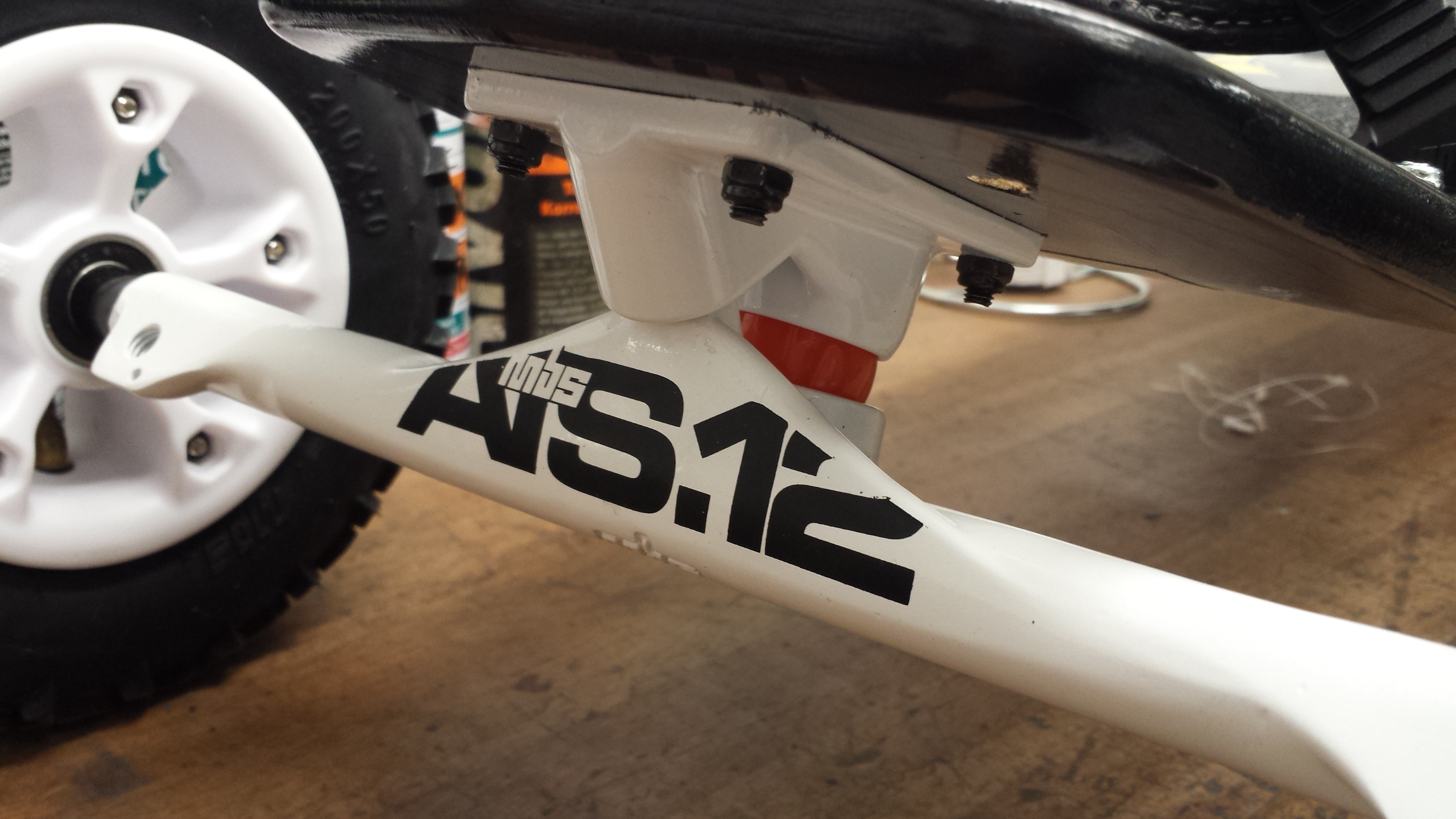
After I rode spring trucks for a year I wanted to try skate trucks. I ride them with the hardest bushings I could find (100 shore) and am really satisfied with them as they are quite carvy and not as progressive as spring trucks:
I’ve been really intrigued by your builds and was hoping you’d post some build threads. I found your other 4wd thread in another forum, but my knowledge of German? is kind of non-existent.
Between racing, snow riding and having hot swappable batteries, you’re doing all the things I’d like to accomplish. Great work!
Finally found some time to continue this build thread:
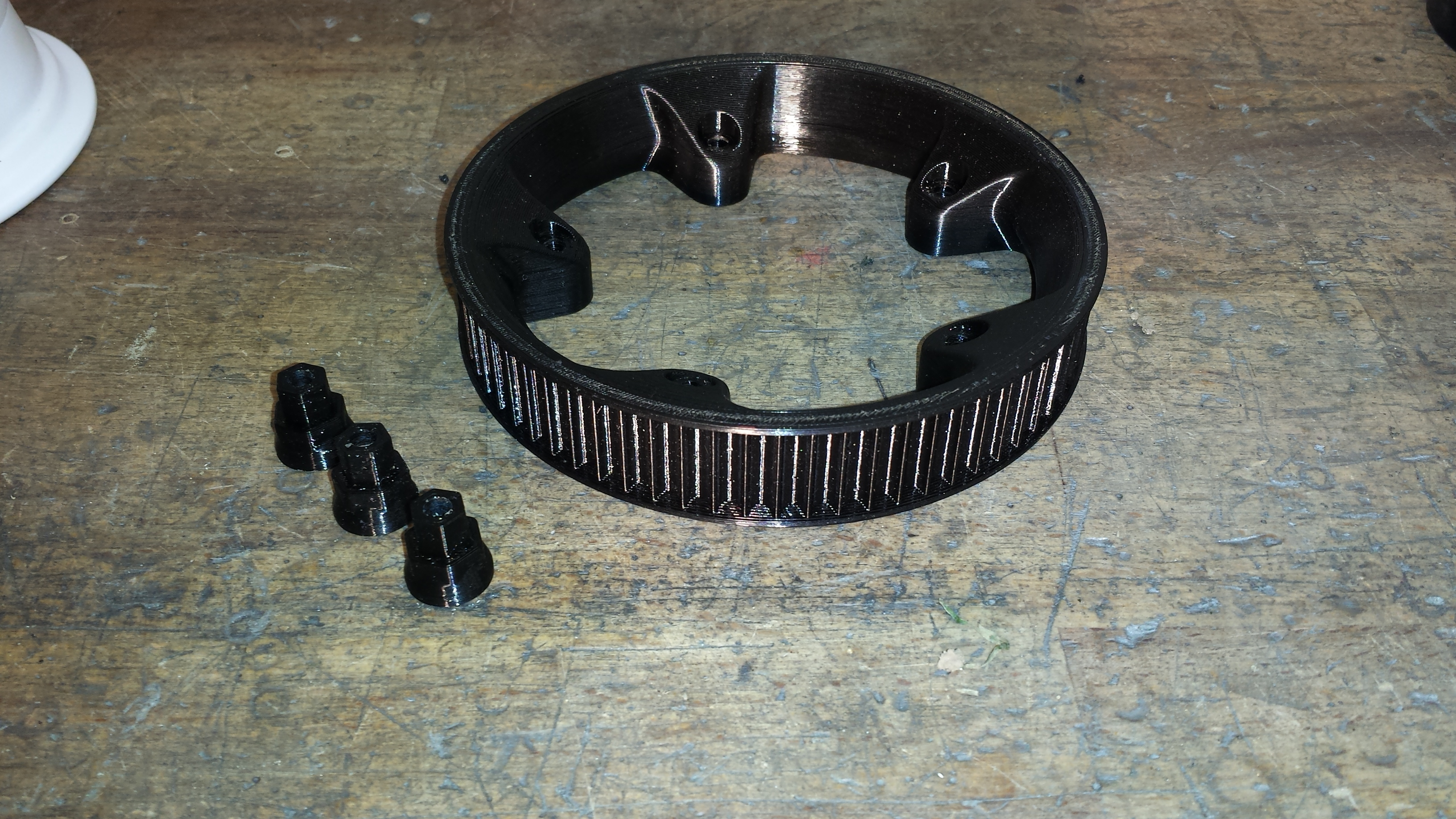
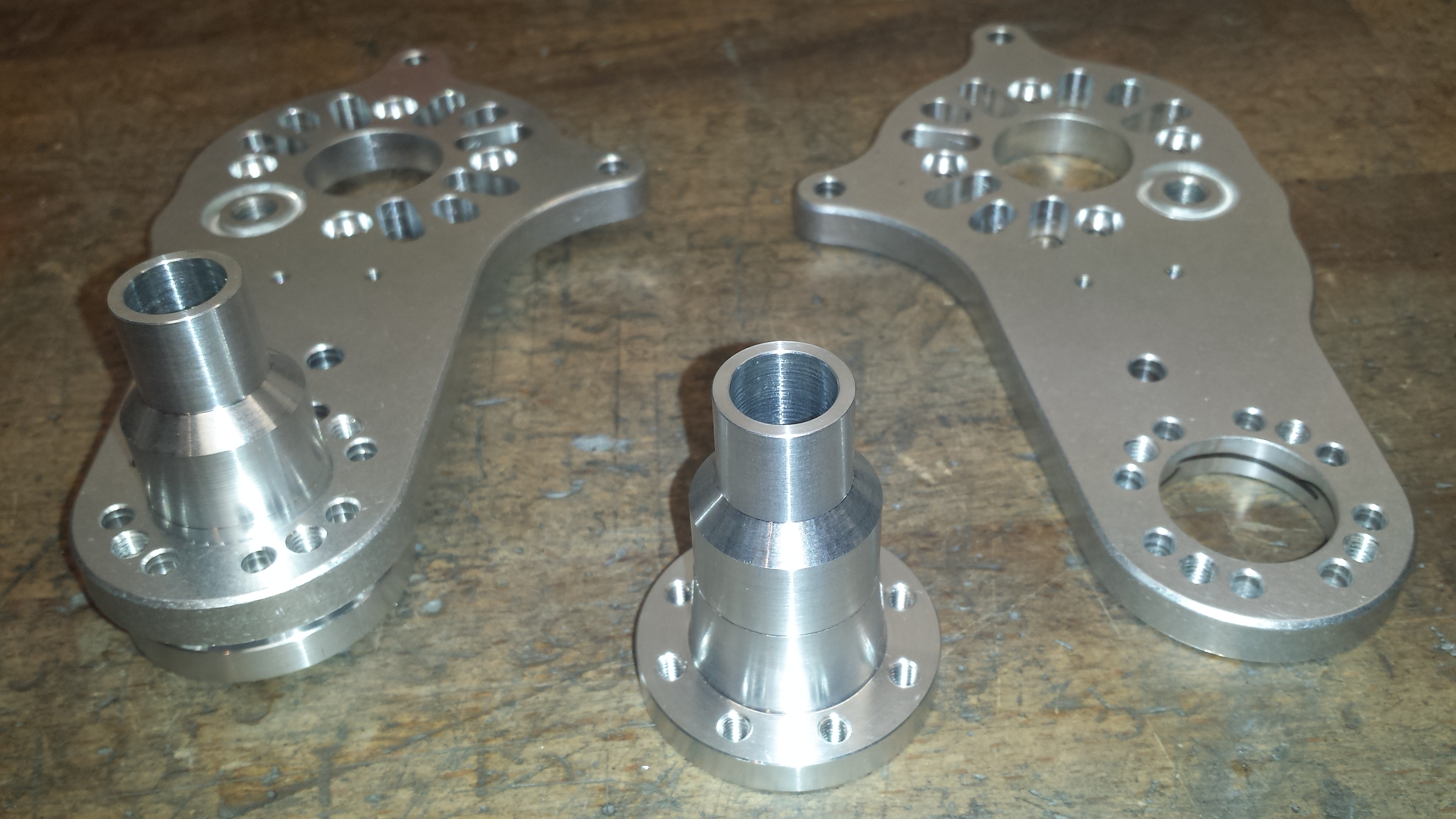
For tensioning the belt I’m using this POM roller with needle bearing. It runs on an adjustable excentric bolt, which sits in a ring shaped pocket of the motor holder. I also added wedge in the clear spot of the belt to keep it from collecting debris and garbage.
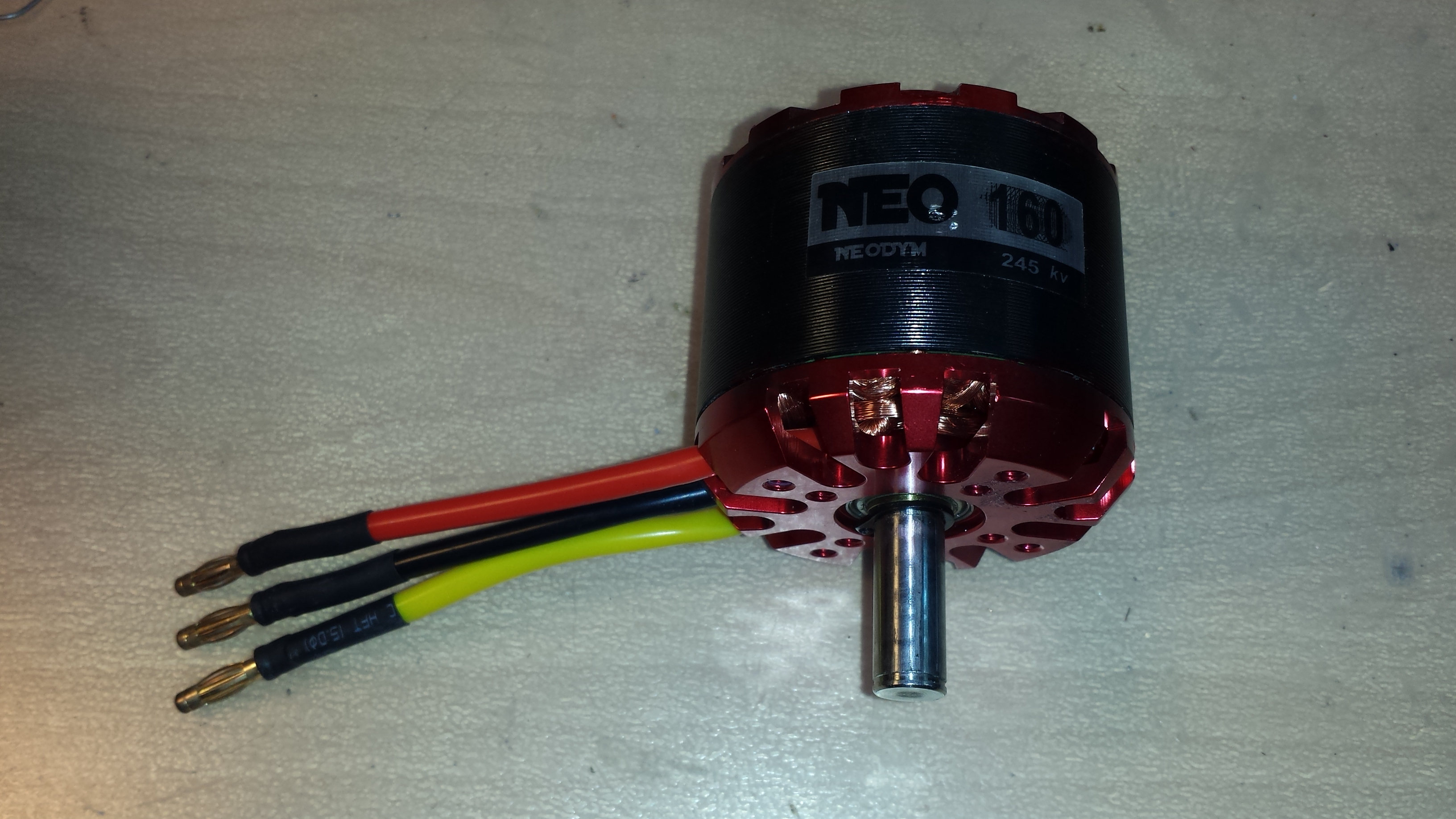
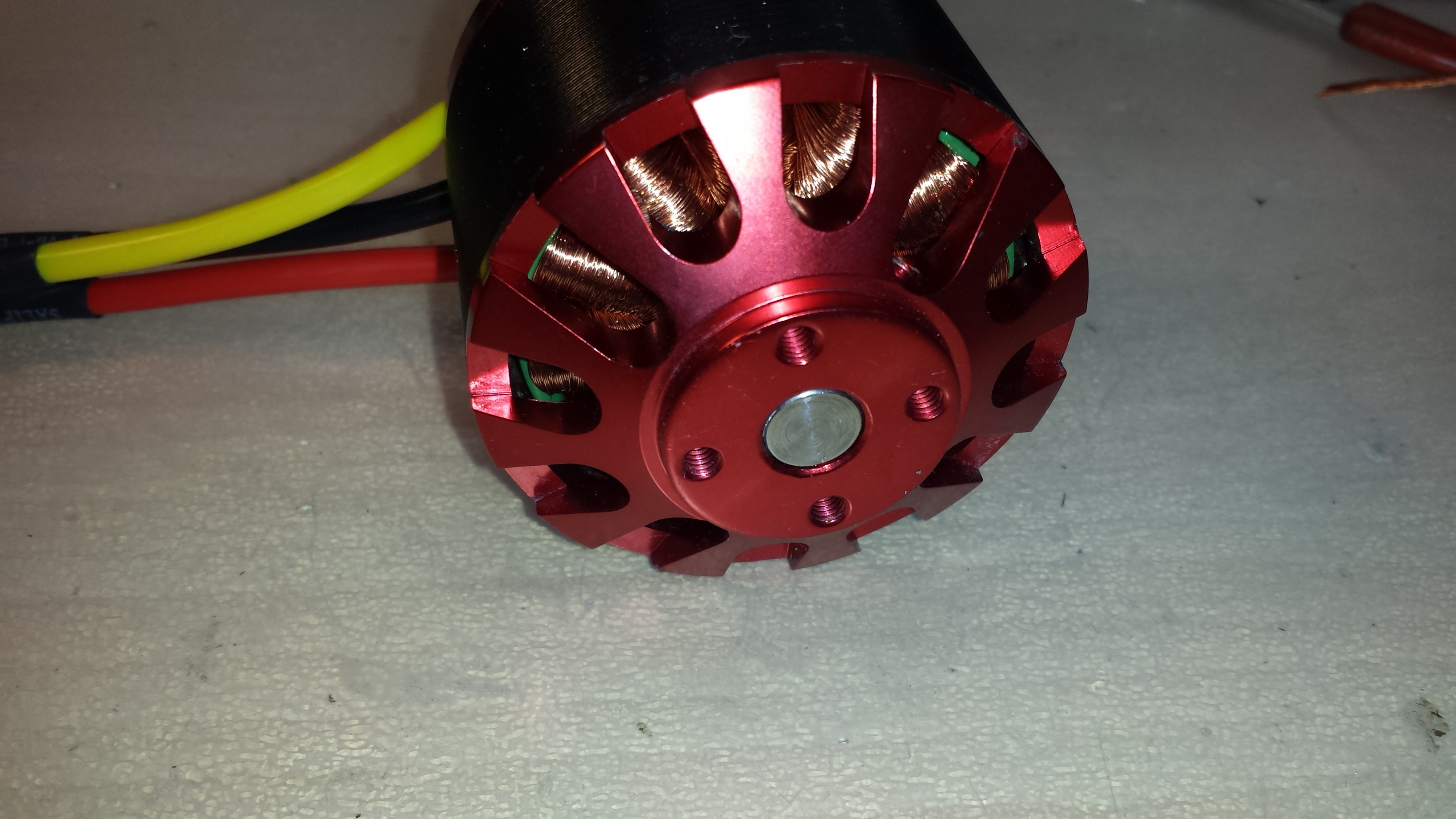
I decided not to go with the usual SK3 6374 motors as they were not in stock as usual and also to save a bit of weight. So I chose c6364 motors with 245kv (measured 230kv) and reconnected them to wye. This results in 133kv with 1,73 times the torque.
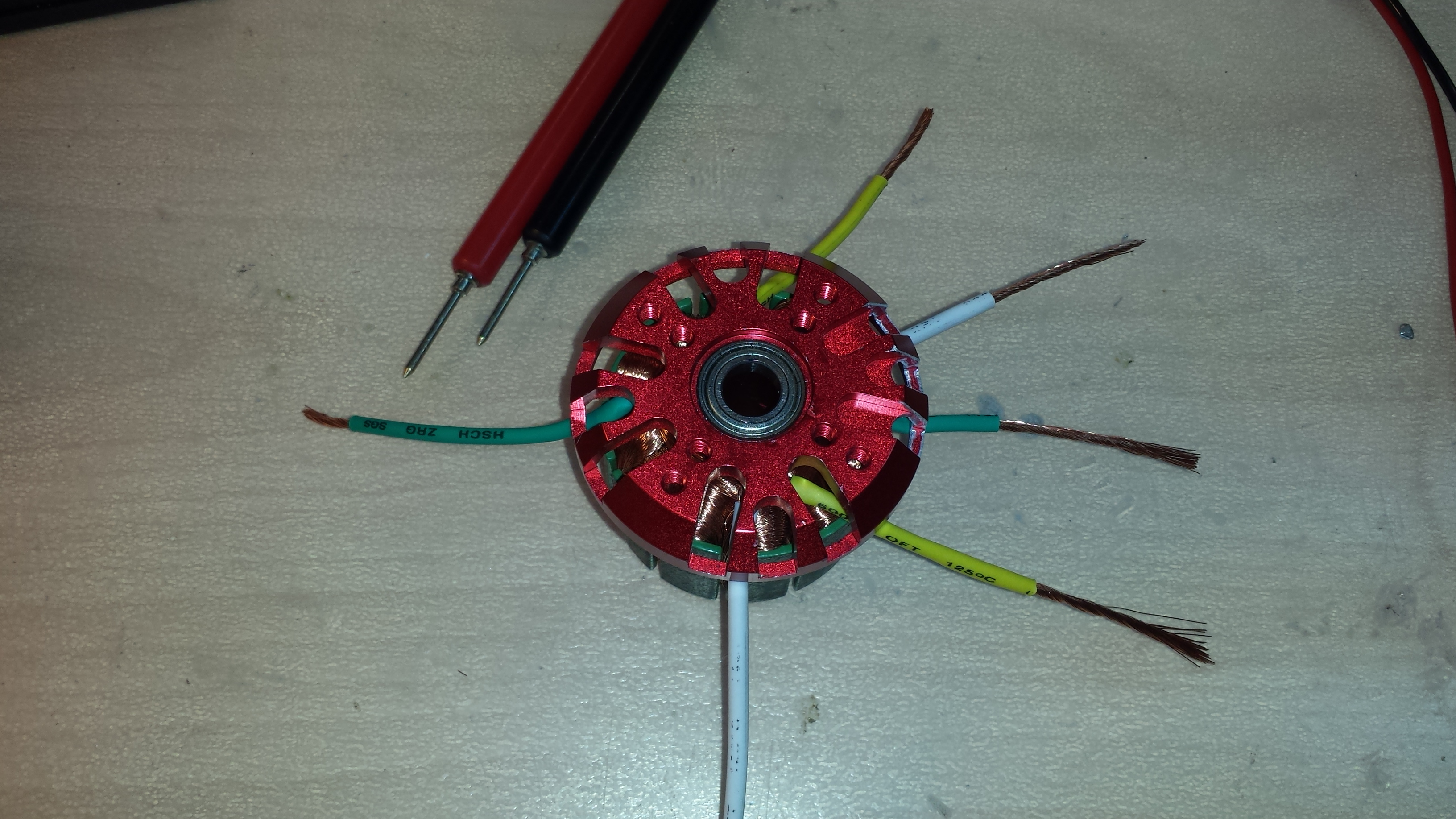
To change a brushless motor form delta to wye, you need to cut the motor wires at the point where the strands are not soldered any more. Then you have to split the strands up to the starts and ends of the individual coils. Rearrange them and afterwards connect all the starts (or ends) of the coils to the center point and connect the motor wires to the remaining connections.
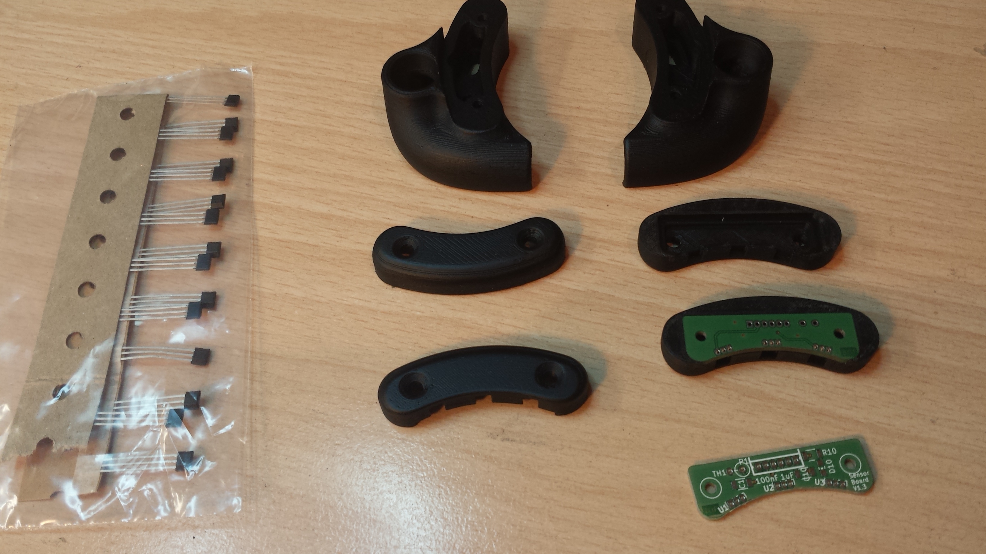
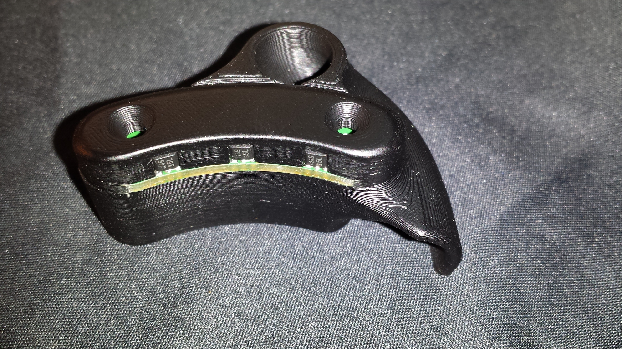
To get maximum torque from stand still without any cogging I went with hall sensors which are placed external in a 3d printed housing that also acts as a cable guide for the motor cables.
@Nowind: Reading this forum from the beginning, but was always too busy or too lazy to document my builds…
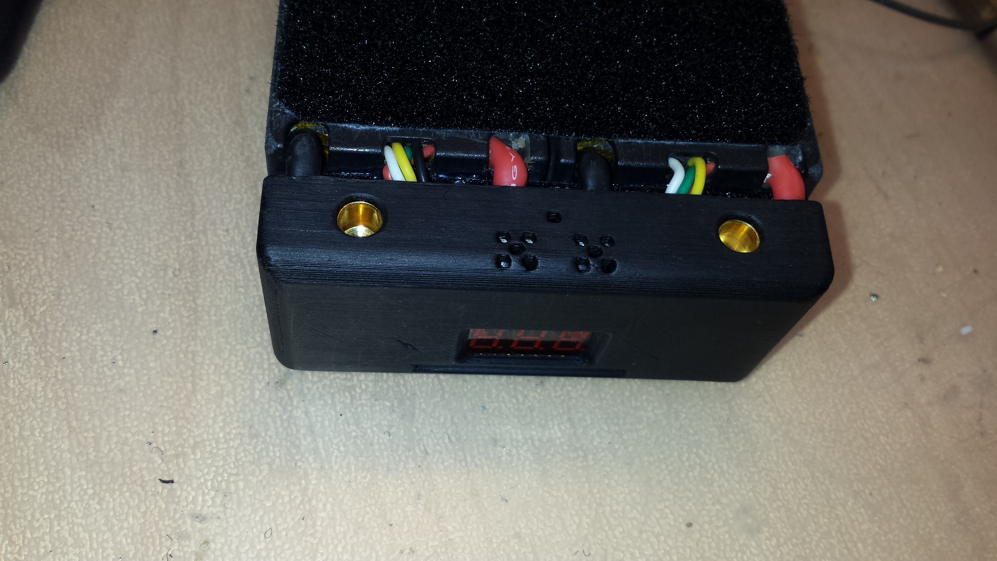
This is the ‘cockpit’ of my board. It consists of a (bicycle) speedometer, a coulometer based battery gauge and a 60V1A LED Step down converter.
The coulometer works just perfectly. You can program it to the nominal capacity of your battery and while discharging it counts the amount of energy pulled from the battery and shows the remaining percentage.
This is independent of battery voltage, so that the value remains stable even if the voltage sags while accelerating hard. It also shows actual voltage (V), amperage (A) and power (W).
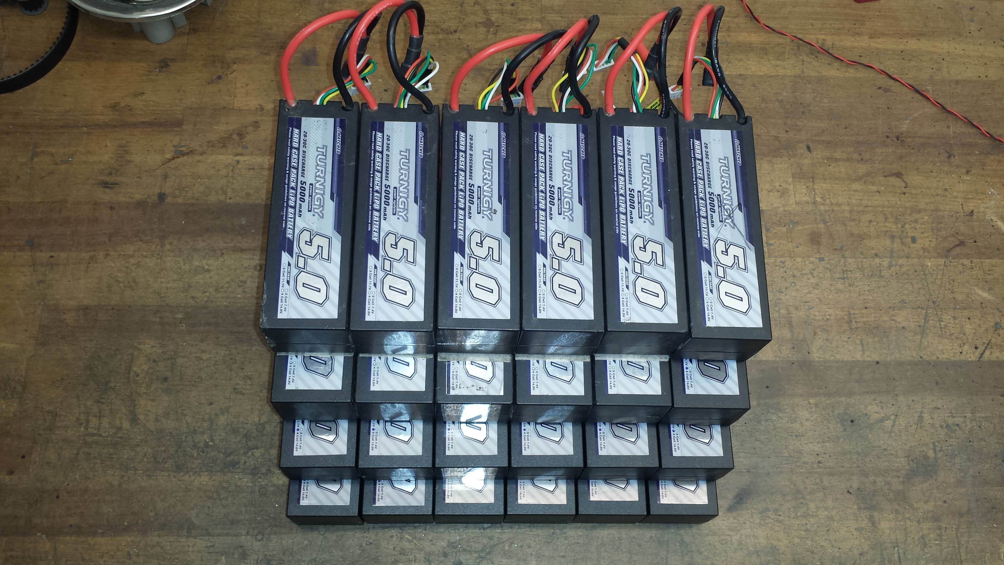
I’m using two of them in parallel to get 10Ah and three of these pairs in series to get 12s10Ah. With 20c discarge capability this results in 200A continuous and 300A burst current.
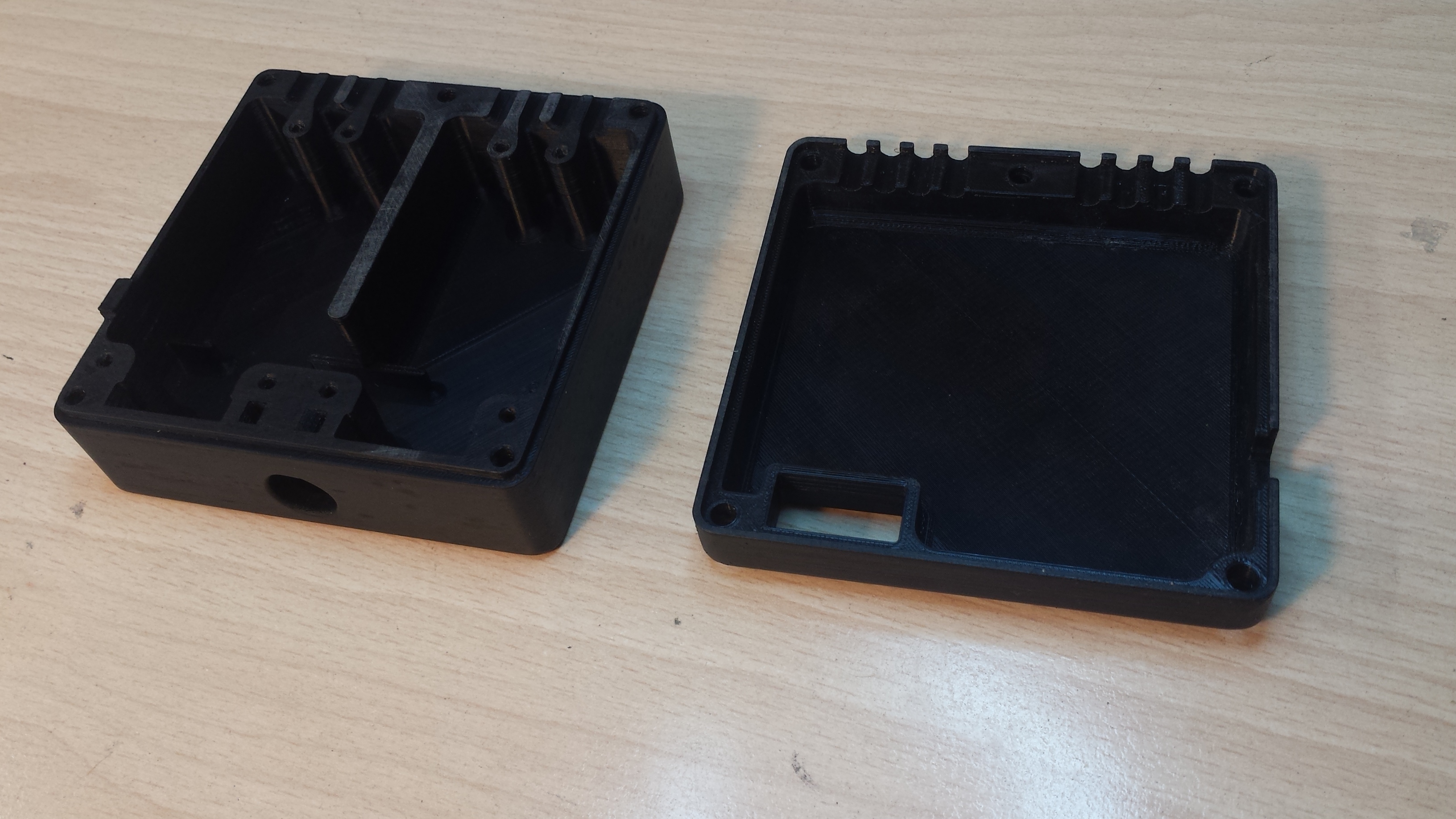
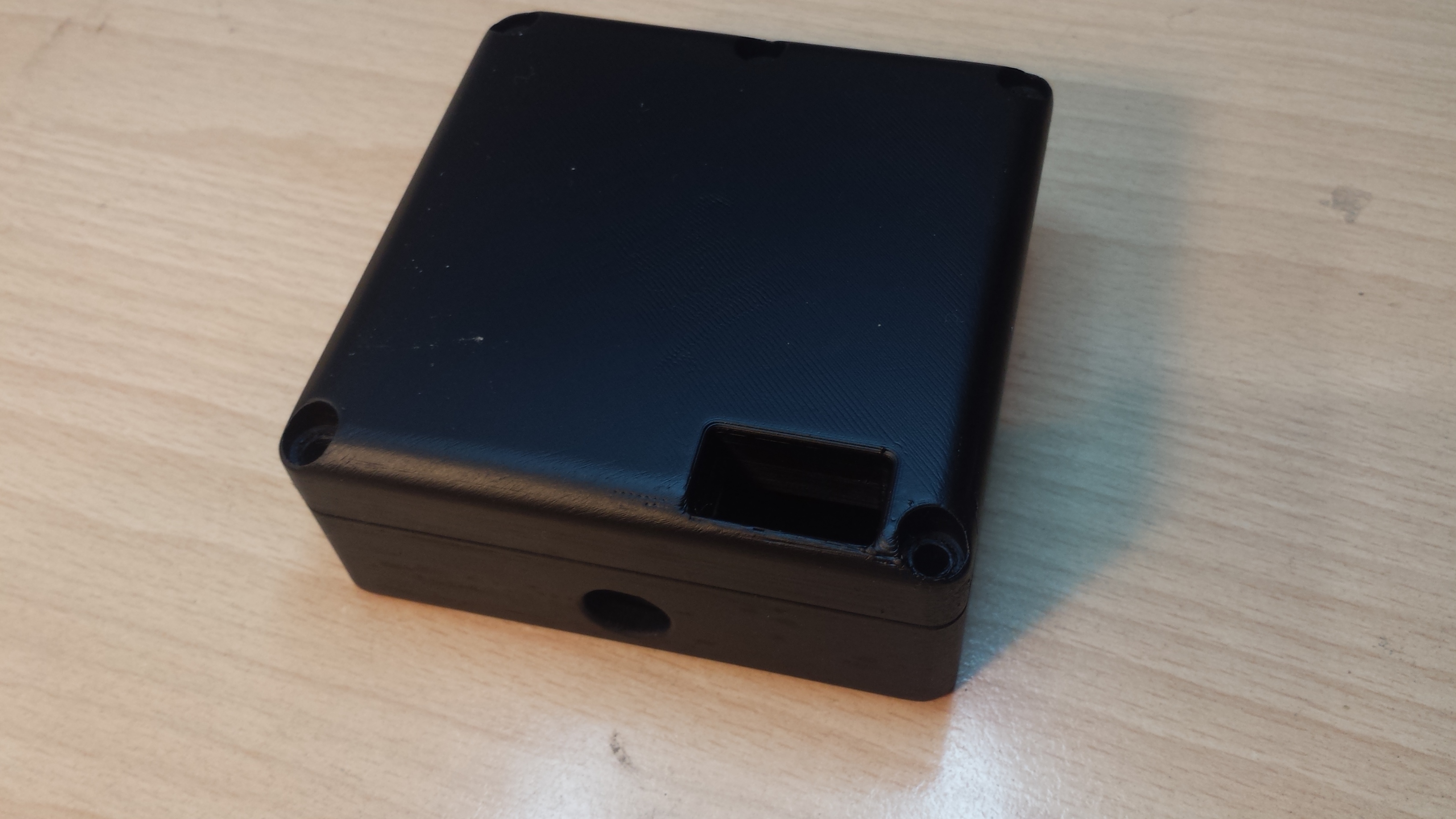
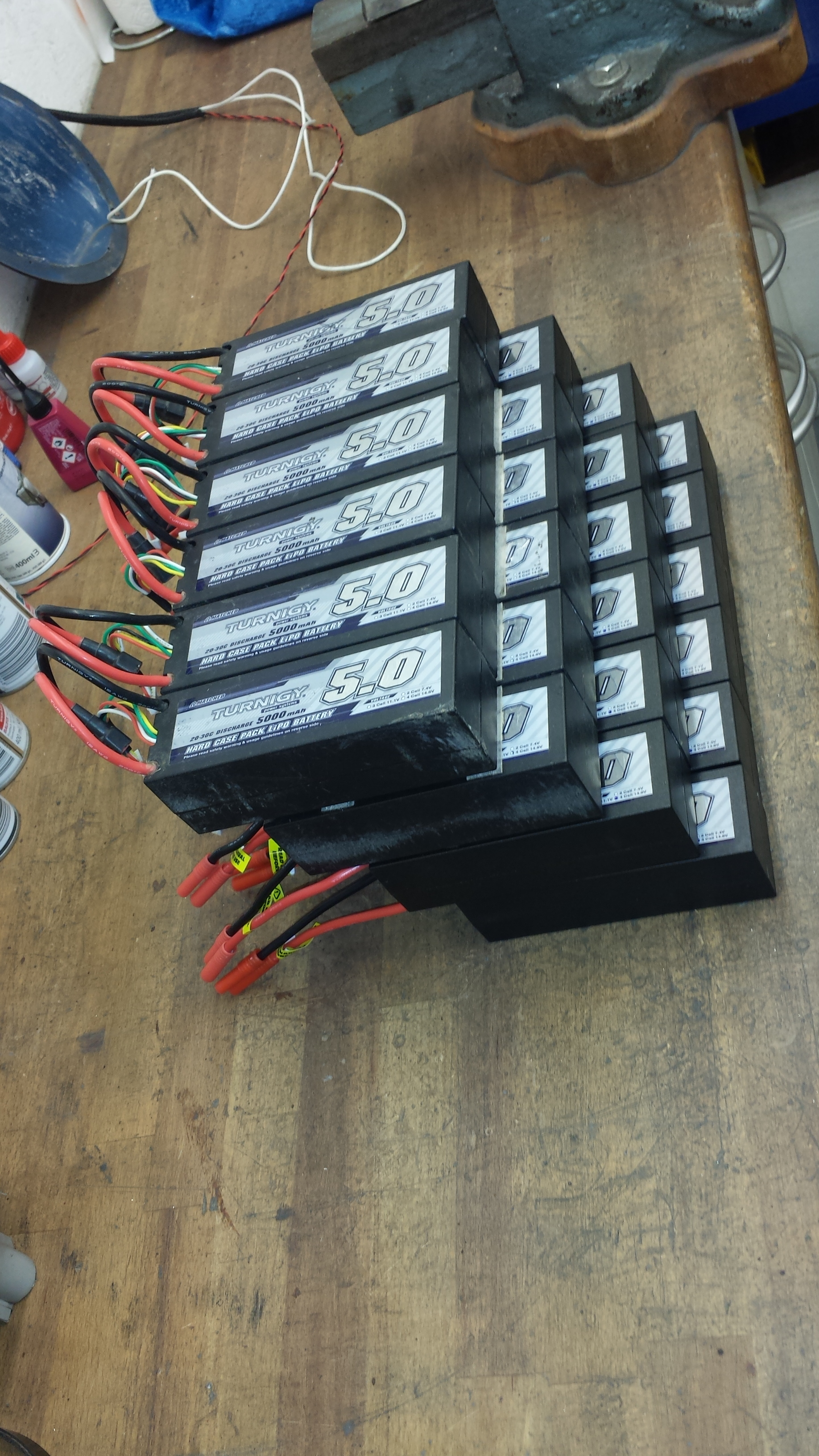
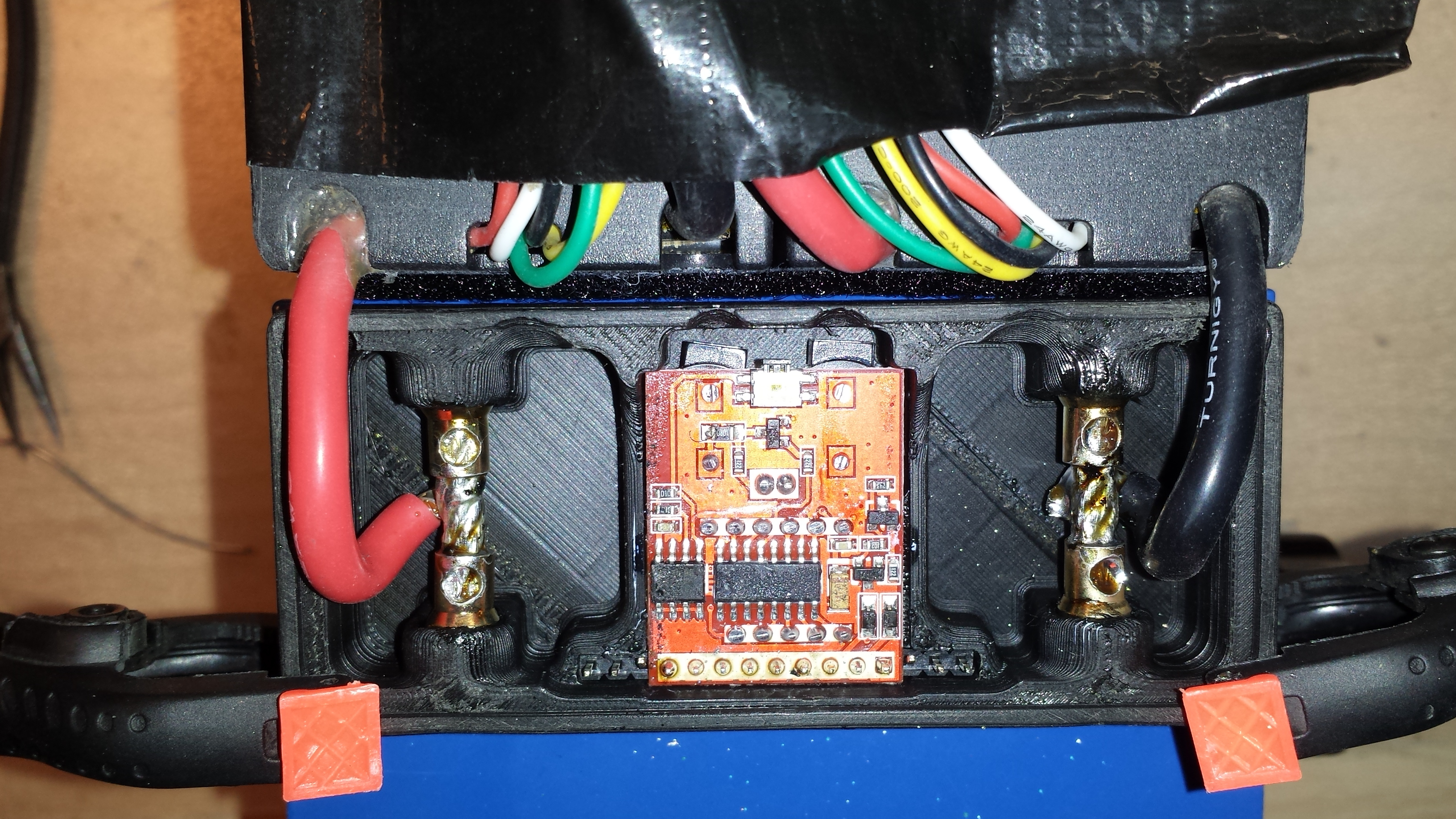
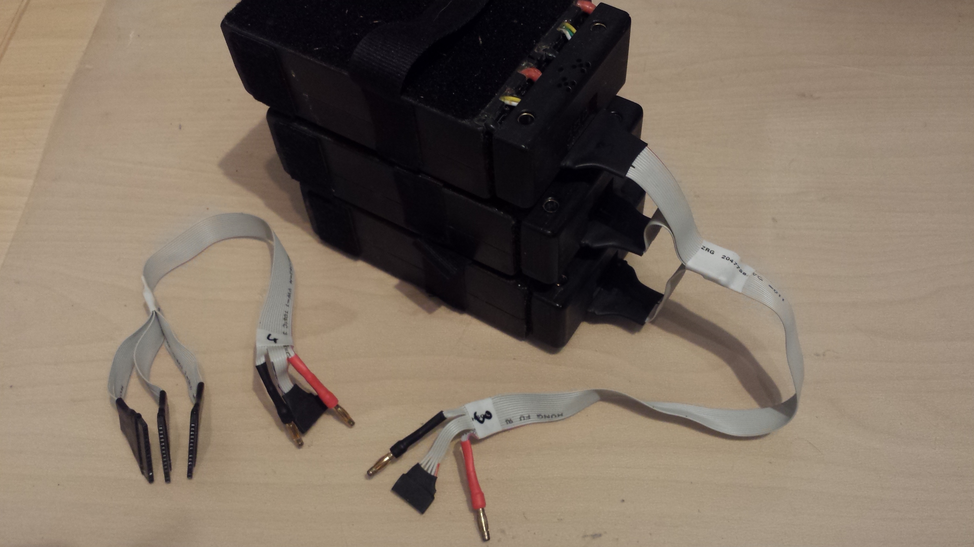
Changing and charging a bunch of these batteries is very annoying, so i decided to build quick change adapters with enbedded lipo saver and charging connector. They consist of a 3d printed housing, a lipo saver with reed switch to get activated by the dock on the board, and 6mm bullet connectors on the bottom and also on the top to be able to stack those packs.
@Duffman Woah, that is some nice battery enclosure crafstmanship, I must say!
Is that circuit board thing in the enclosure just a voltmeter or something more?
These ‘‘stackable’’ / easy to remove batteries is a dream of mine! lol… I wished a lot of times that my battery had some easy to disconnect connectors, so that I could remove the battery and bring it to charge like the commercial boards have… it is a hindrance to take your board everywhere with you, just to charge it up…
–
Have any pics of how these battery pack’s now connect to your board directly?
You can see the battery swap in this video at 3:05:
The battery adapters have an included charging port which combines power leads and balancing leads to one connector. I made 3 in 1 cables to rearrange my 3x4s serial - (12s10Ah) packs to 3x4s parallel (4s30Ah) to be able to charge it with a cheap 4s charger. I own a quadro B6 charger, which is able to charge 12 packs at once with this cabling. (4x 3x 4s10Ah)
The male to male 6mm bullet adapters sit in between when stacking batterys to increase capacity.
The ‘dock connector’ on the board consists also of a 3d printed housing which holds 6mm bullet connectors to connect the 3 individual lipo packs to series. A magnet is embedded in a slider in the middle pocket to activate the packs’s lipo saver by a reed switch when the pack is inserted.
After the first test rides I decided to mix up the parts of my boards a bit. Originally my ‘monster’ had the shorter Pro 90 bamboo deck which is lighter, stronger and has more pop. The Core 94 deck is a bit longer and stiffer.
So I took everything apart again and used the Pro 90 for the ‘race board’.
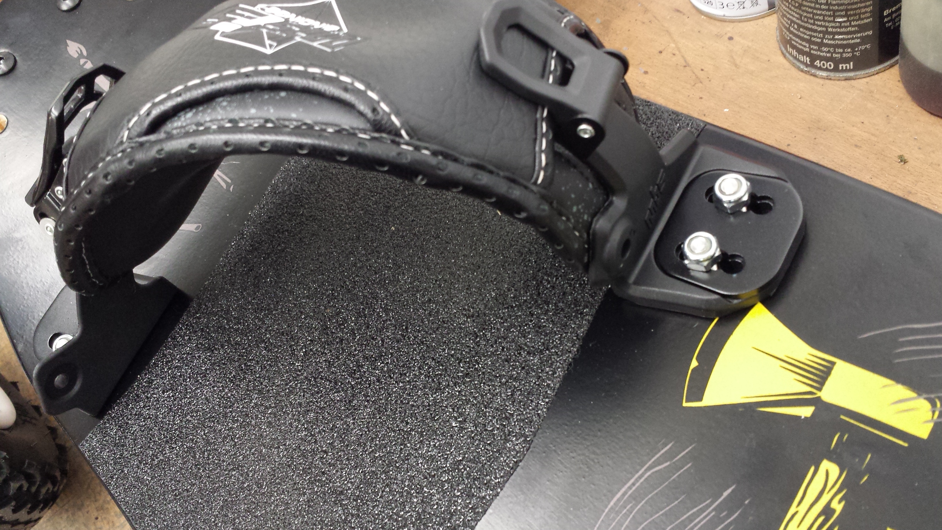
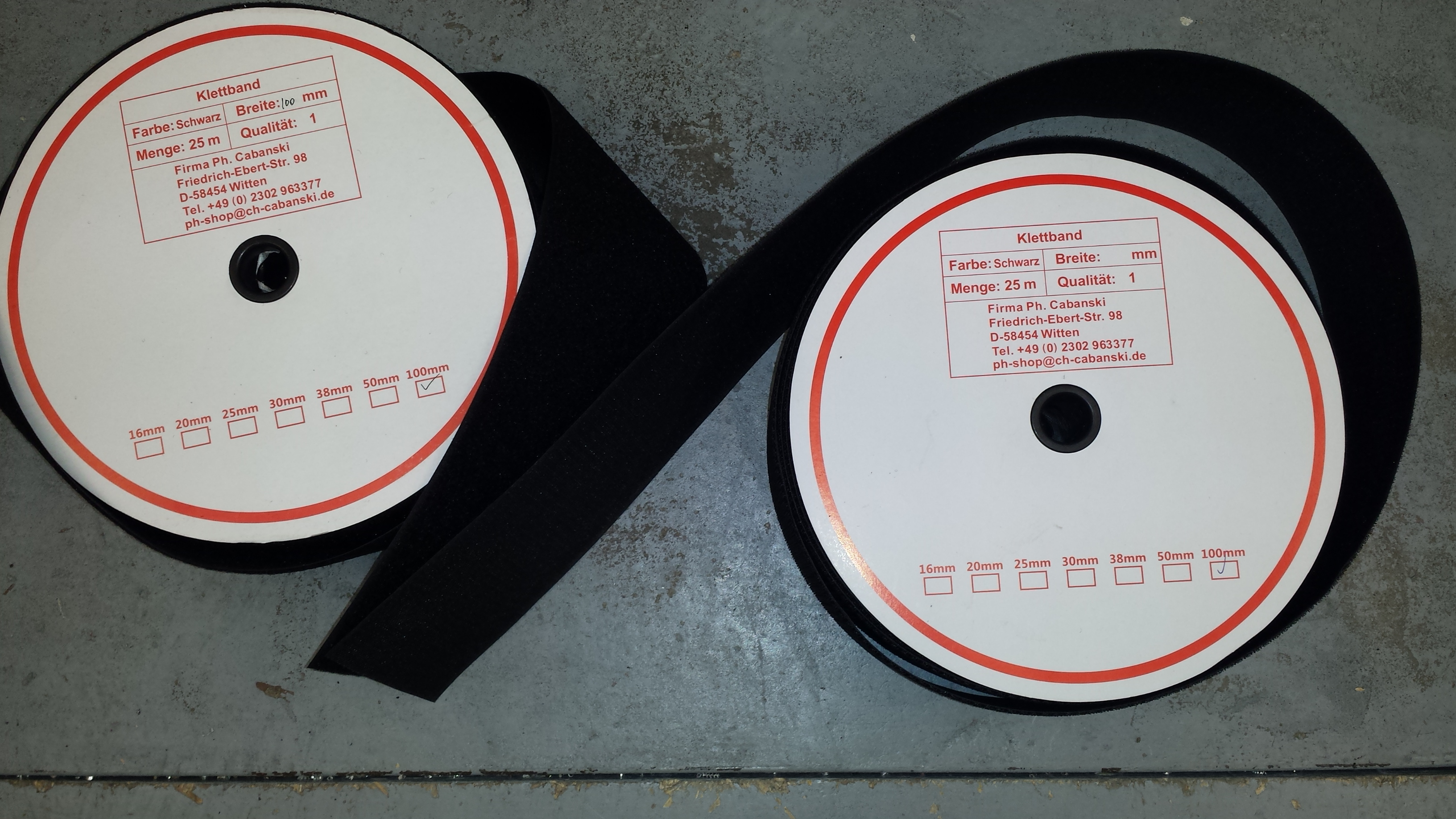
As I did not like the print I covered nose, tail and the middle of the deck with velcro to hold the cockpit, the ESCs and the batterys. The foot rests got new Viscious grip tape.
After the first test rides with this setup I had to improve a few things:
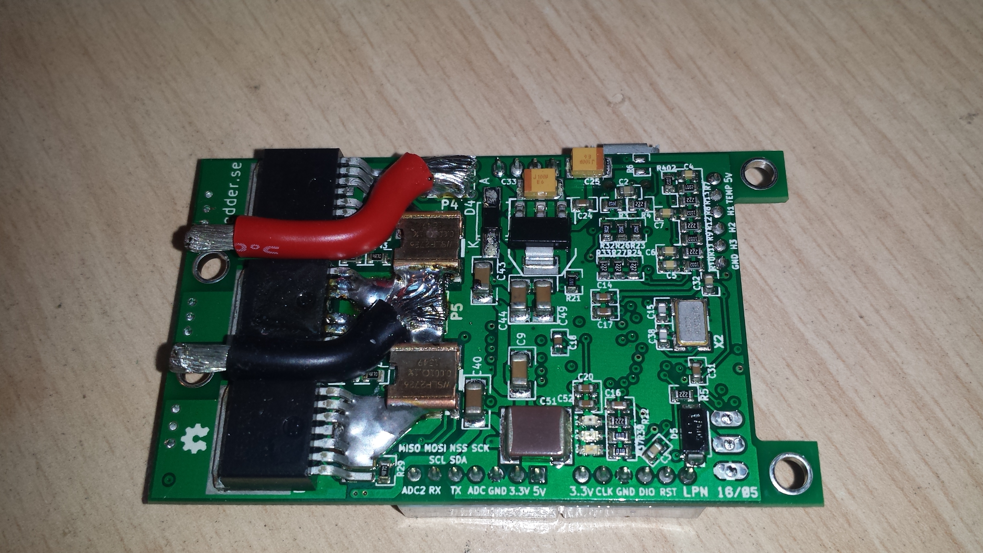
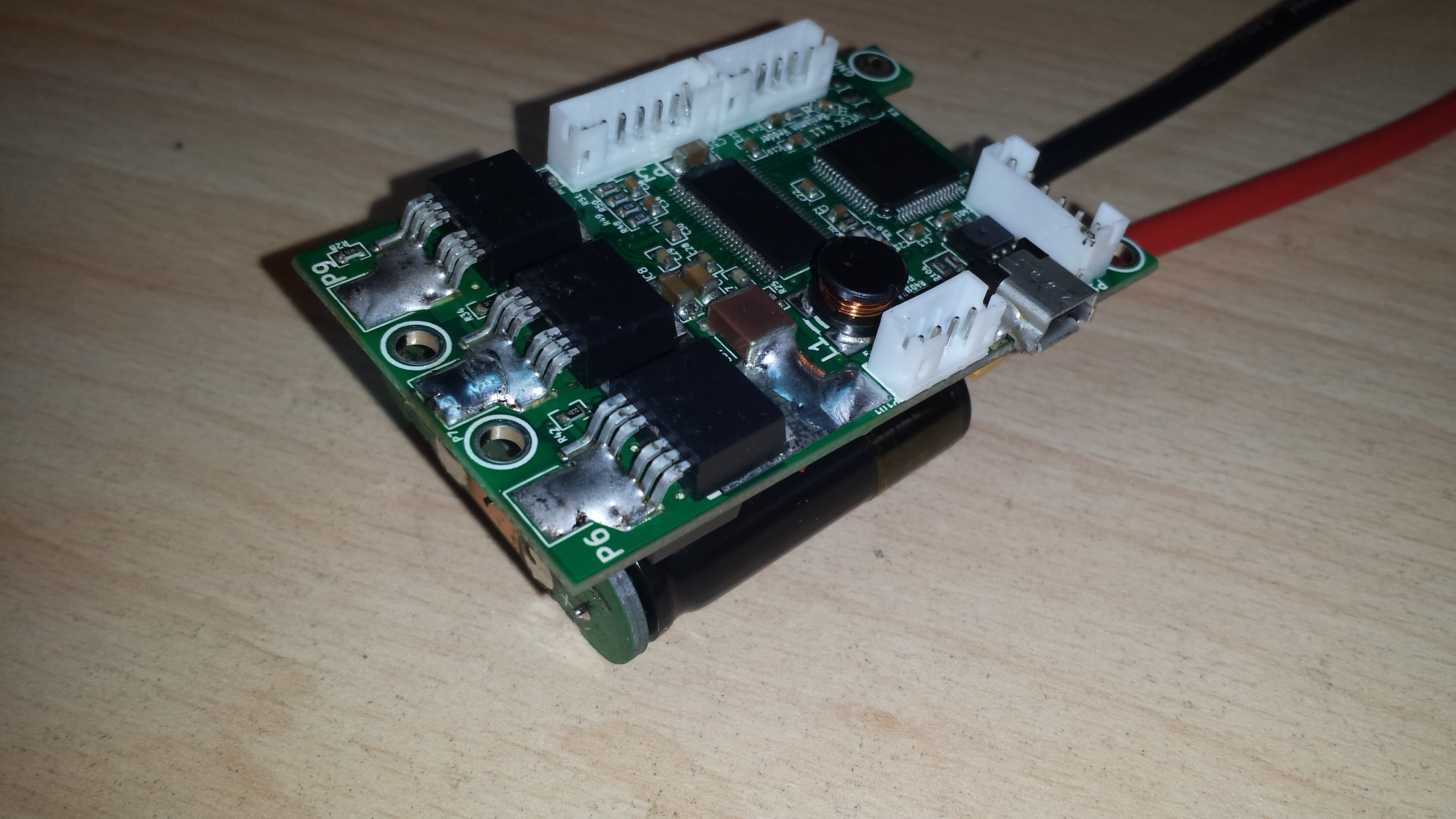
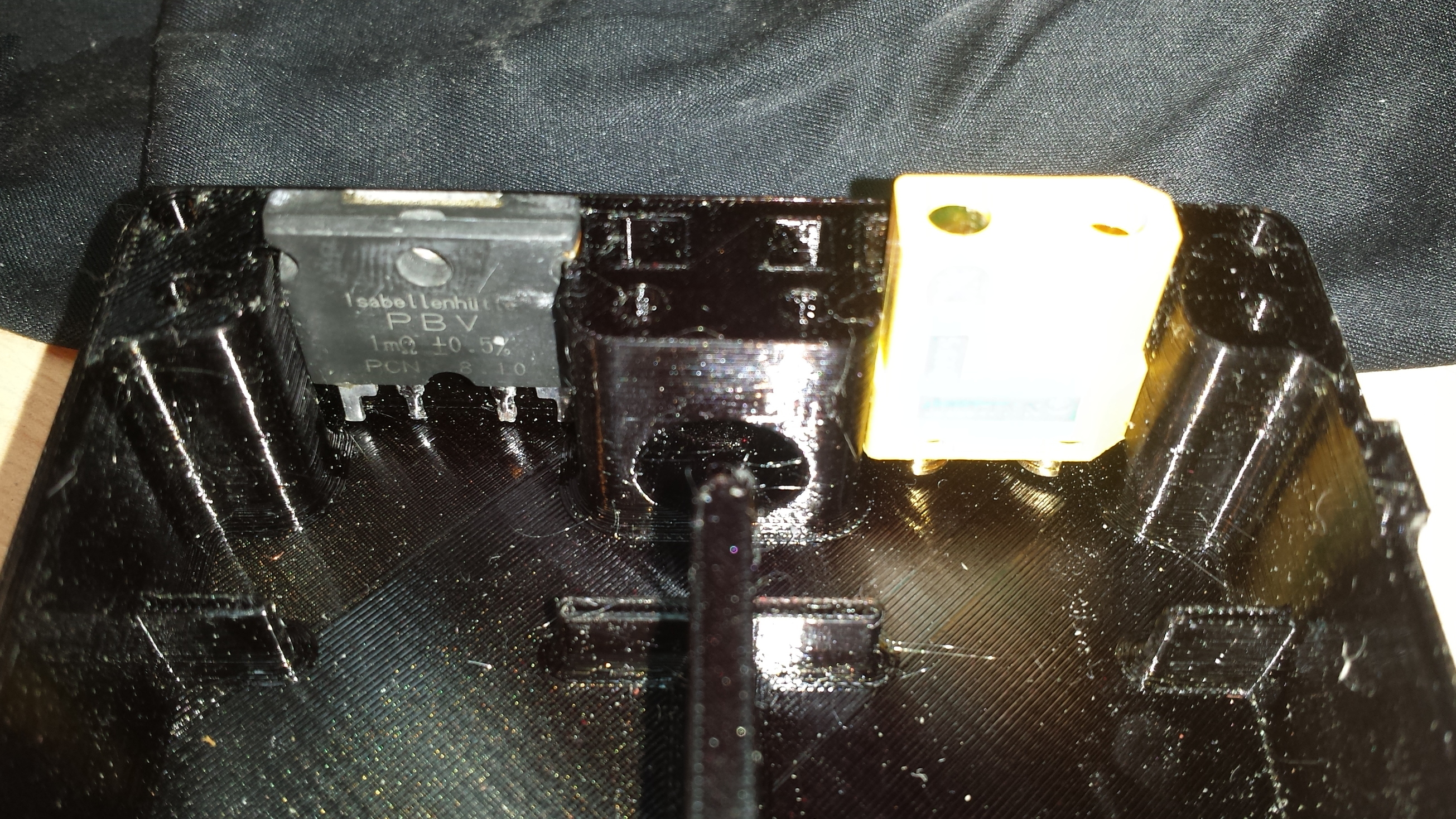
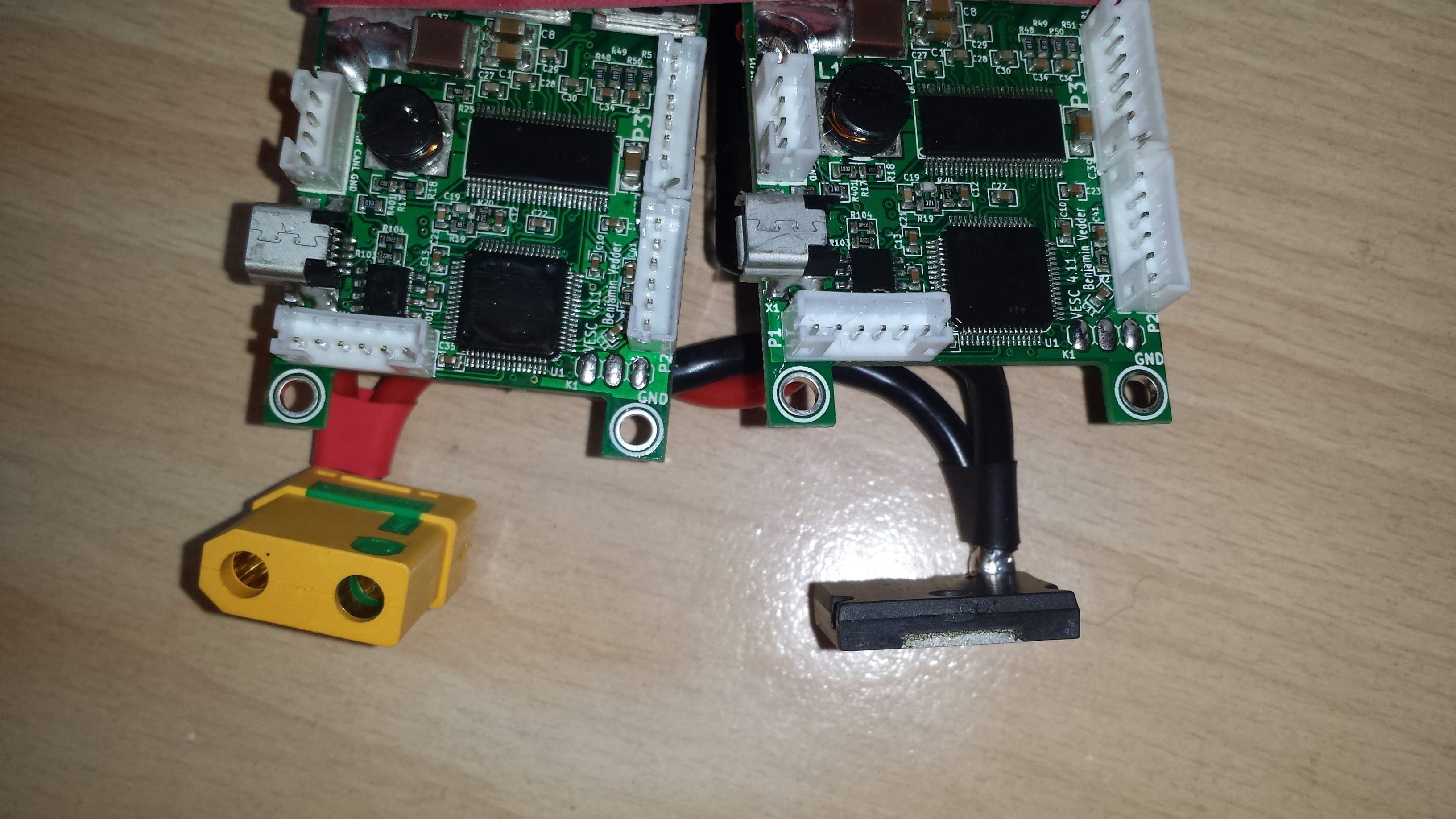
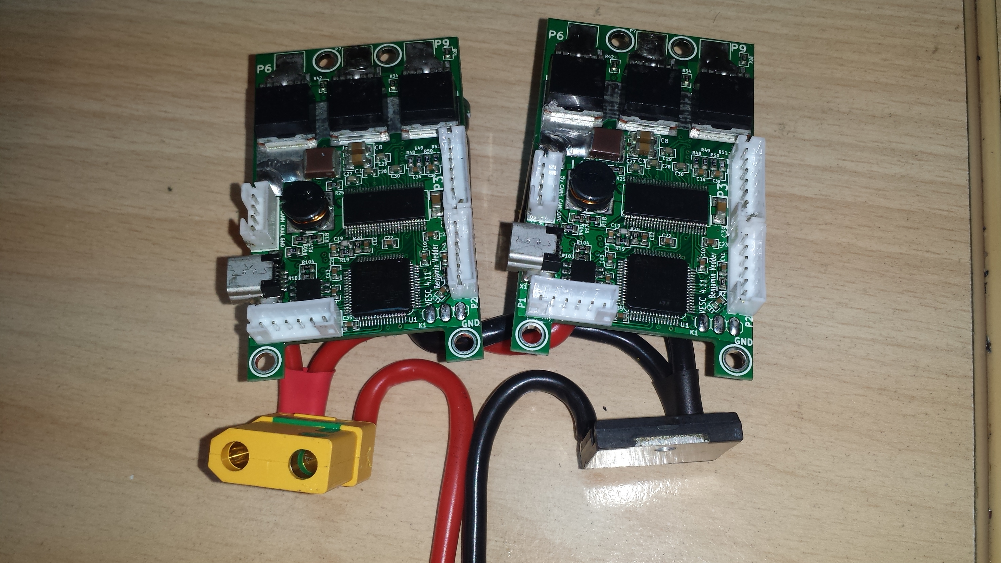
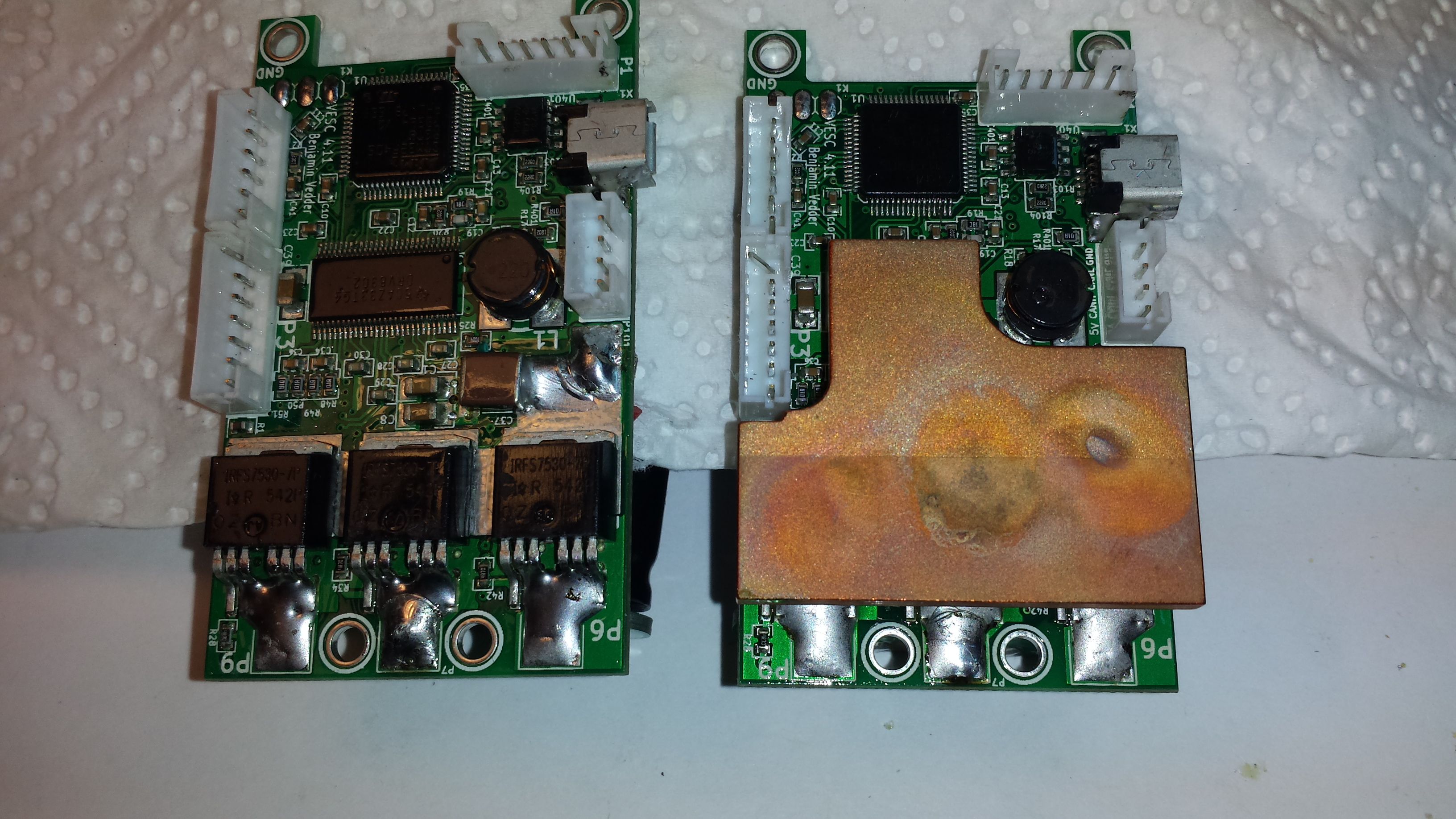
When riding hard, I hit the temp limit of the VESCs which were sitting good isolated in the small case. So I had to rewire the electronics and improve the thermal design. At first, I replaced the stock caps with ones with lower ESR:
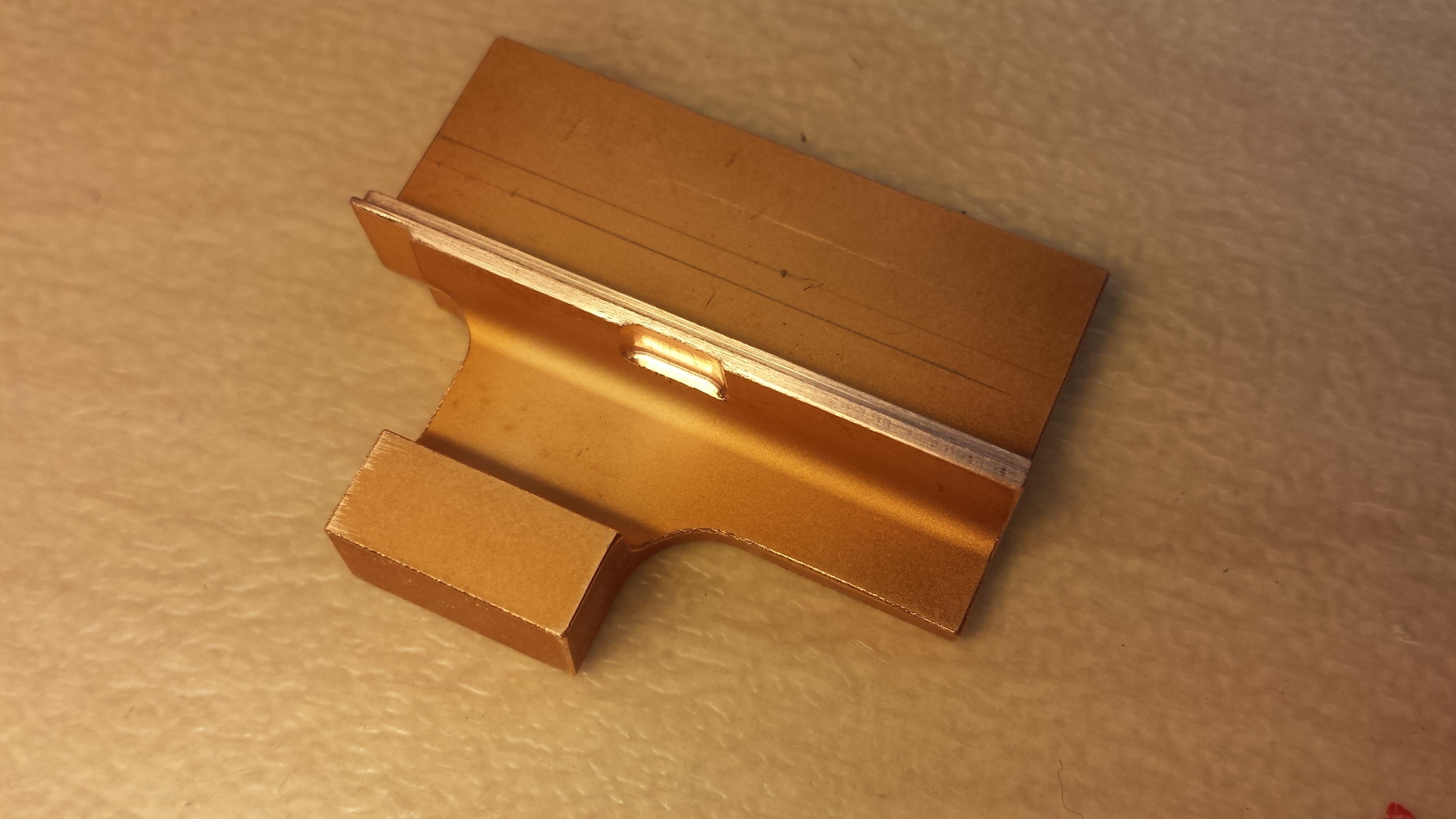
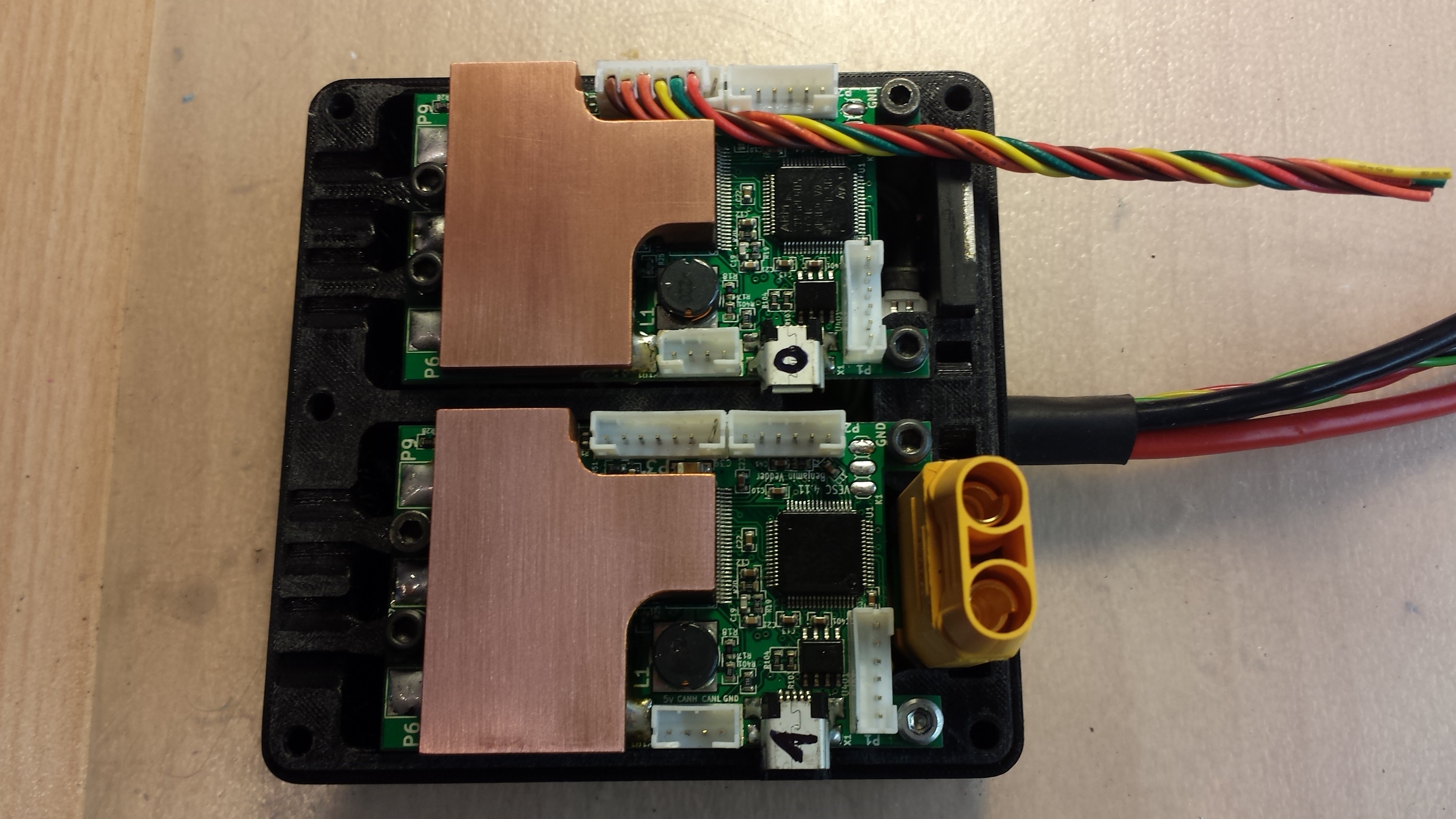
And finally topped with a copper heat spreader, which is soldered to the positive side of the FETs toget direct metal contact for lowest possible thermal resistance: http://www.thingiverse.com/thing:1853104
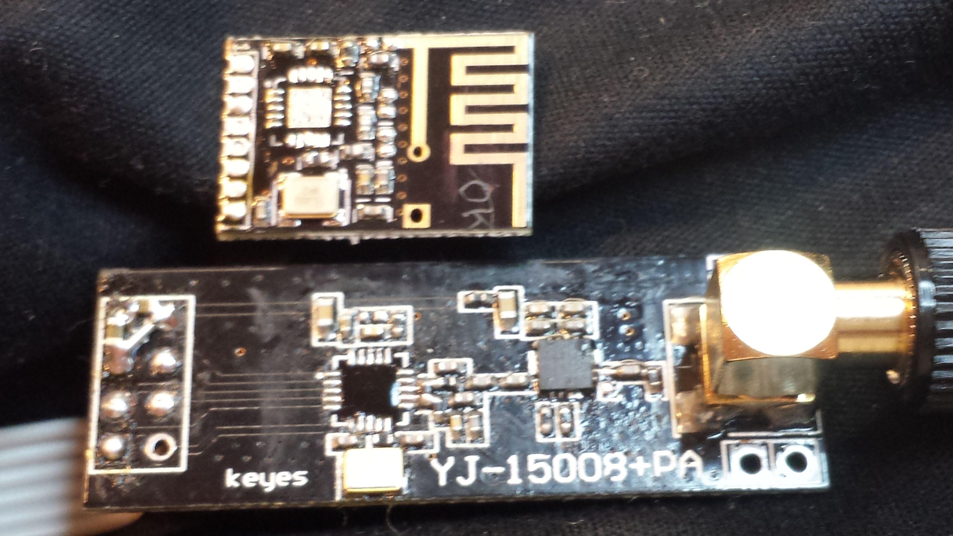
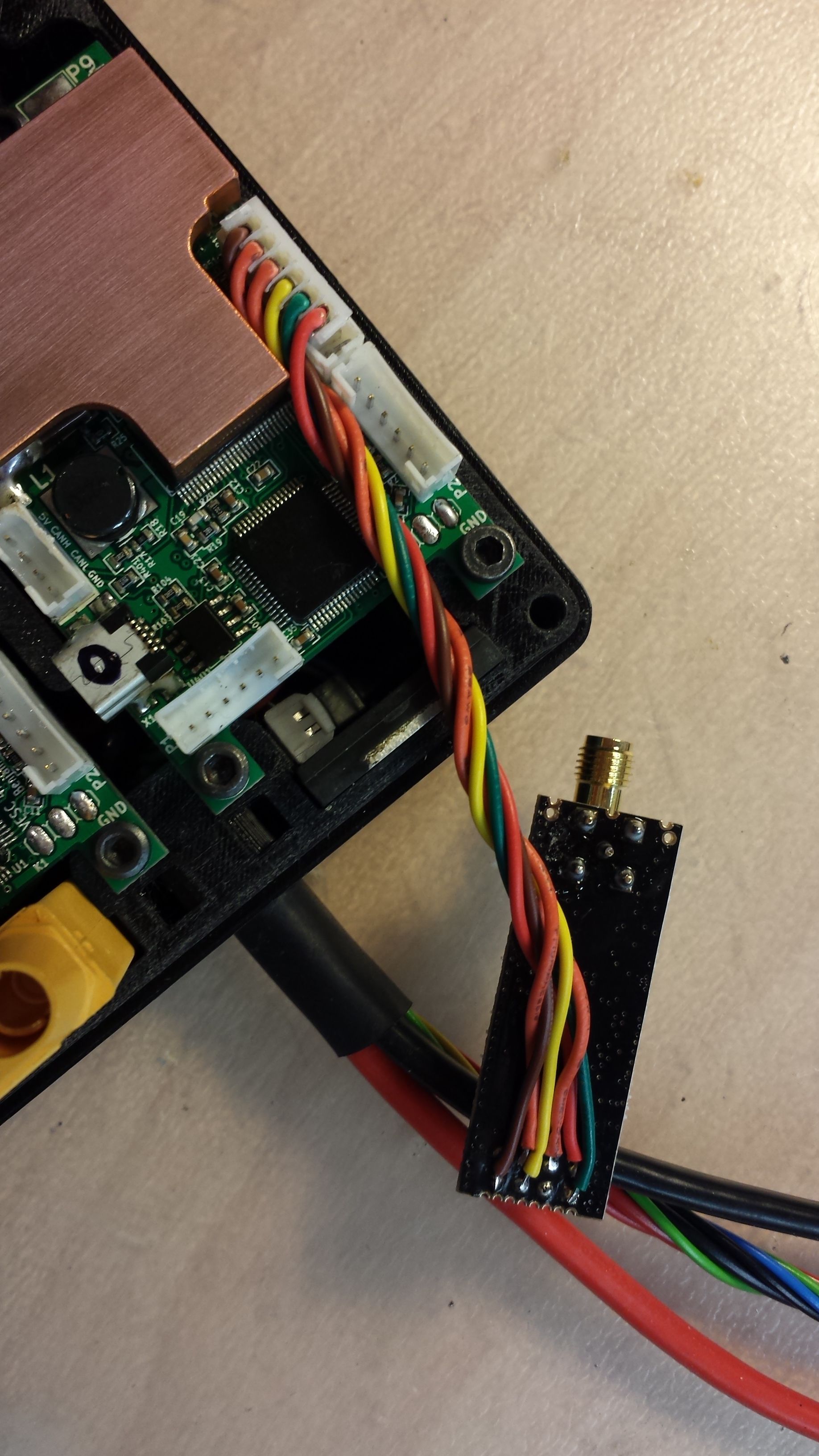
The next big improvement was the switch from the Kama nunchuk to a NRF nunchuk and later to my NRF hand controller:
The small pcb is the standard NRF transceiver, the bigger one is the ‘long range’ version with added PA. The normal ones still produced some glitches at high currents, so I had to go for the long range modules for sender and receiver.
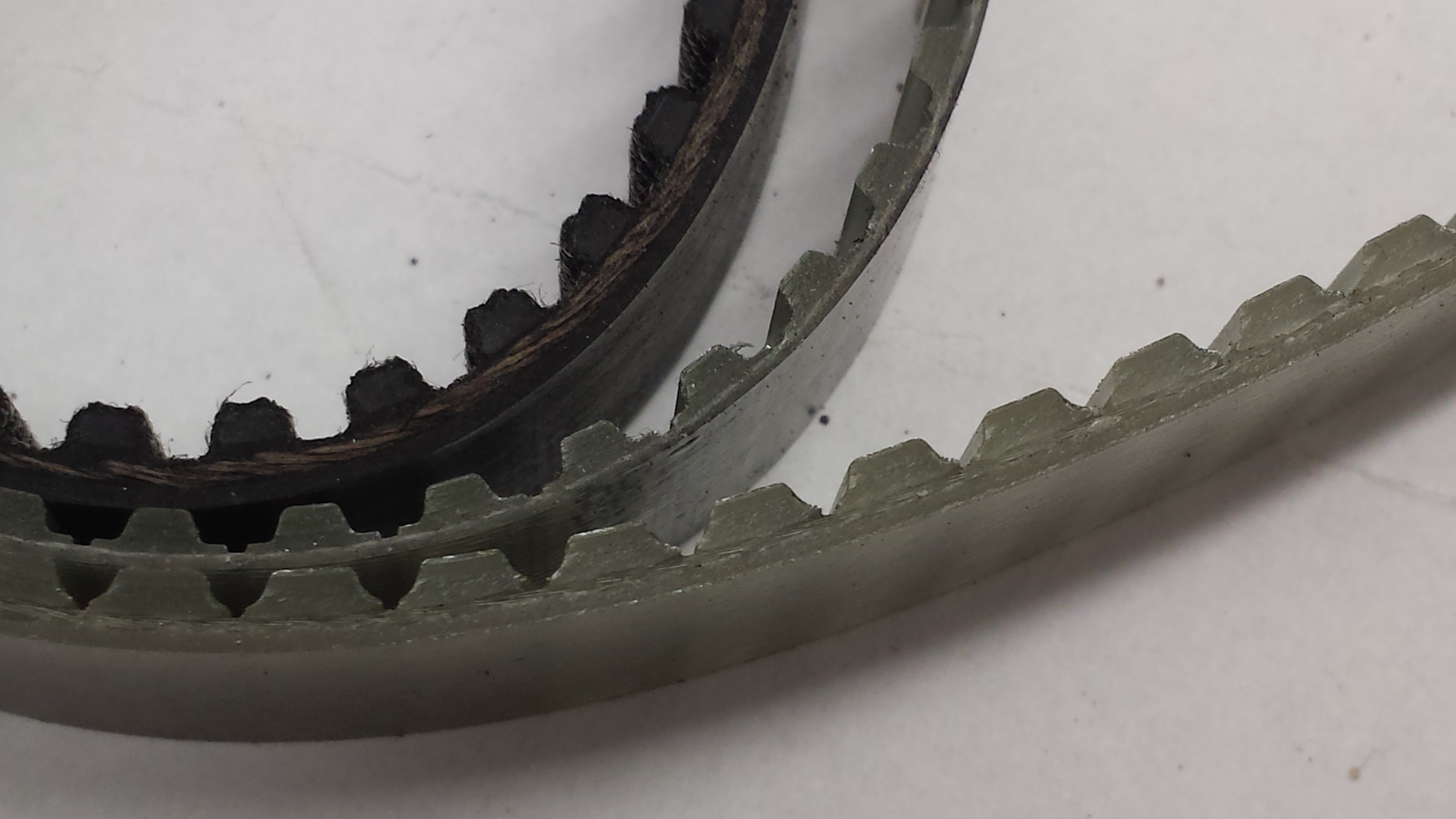
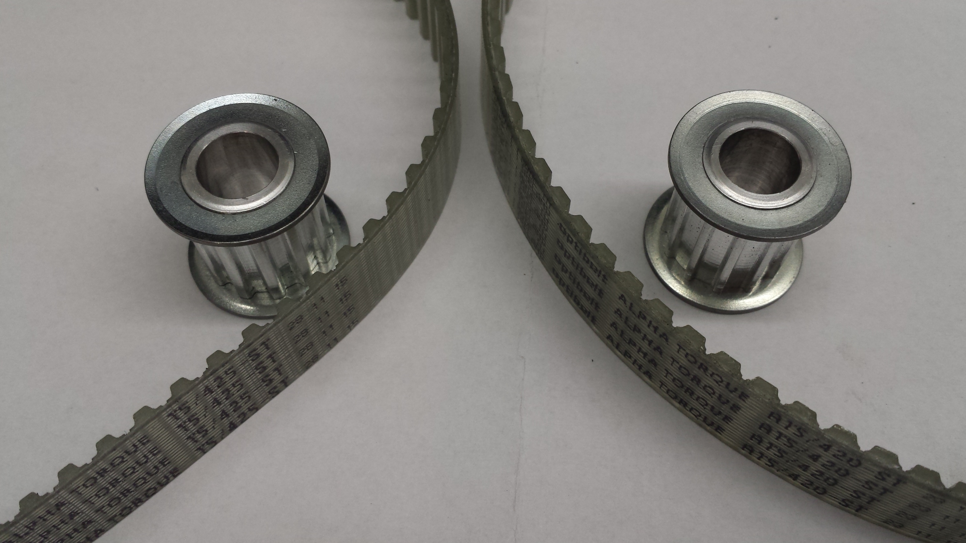
The initially used HTD5m belts in 15mm width could not hold up against the motors and got ripped every 10 km. Therefore I tried T5 and AT5 belts, which have 2x / 3x the tensile strenght of HTD. Even more important is that they don’t fail instantly like HTD, but get louder and louder, loose teeth or get spliced and remain still rideable for tens of km.
How exactly the htd5 belts got ripped apart?
Also - is it “uncomfortable” when belt gets ripped? I assume by using 2 motors u dont get to feel this as much as if u had only one motor / belt.
Did u have to upgrade teeth count of motor pulleys or the idler worked just fine for these ‘T’ profile belts? The ‘ridges’ which should grasp the belt look way more shallow than they are for Htd5 belts/pulleys
–
Concerning heat management - how big of an improvement gave that ‘heatpad’ over the fets/drv and then exposing the whole ‘assembly’ (heatpad + heatsink with fins) to the outside / wind?
Have u logged any data for this or it was just more of a ‘experience’ that fets didnt get heated up as much now after the ‘mod’?
Some HTD belts got ripped by accelerating or braking hart but some broke just while riding. With two motors you can at least ride somehow home…
I was able keep my reduction same, as the different profiles were available with the same or almost the same teeth count: HTD 85t, T5 85t and HTD 84t
The pulleys have to be replaced when you switch between the belts because they have totally different profiles.
I’ve not logged temperatures, but before the mod the VESCs ran easily into the temp limits , so around 100°C and after the mod they only barely get warm lets say 30-40°C. I’m going to add a bt module to be able to log properly…
Interesting experience you got with htd5… at what power levels were you running your board? I assume this was for the ‘‘smaller one’’ - MBS one, which is mentioned in this thread, right?
It does sound scary that a belt might break apart when accelerating… I assume it could create a nasty ‘‘snap’’ that might propel one forward as the acceleration is lost suddenly once the belt breaks…
But yeah… if the belt breaks at moderate speed / acceleration it does not sound as bad / scary.
With tooth profiles I meant it more for the motor pulley, as it is a bit smaller… but I assume this does not change much for you… as you got quite high ratios anyway… and this might be a bit worse for ‘‘smaller’’ ratios.
–
The temp difference you mention does sound like a very big / major improvement
All of that… ^^
I have a few designs floating through my head: helical gears, planetary gears, internal gears…
But I don’t think, that I will change this board. Maybe for one of my next builds…