Does someone have a schematic of maytech sensor cables?
I´m using Polar´s 6355 sensored motors with 6 sensor cables, but not sure how to connect them.
Not having a fuse atm, so I´d like to skip the trial and error and jump directly to the connect-and-working-part 

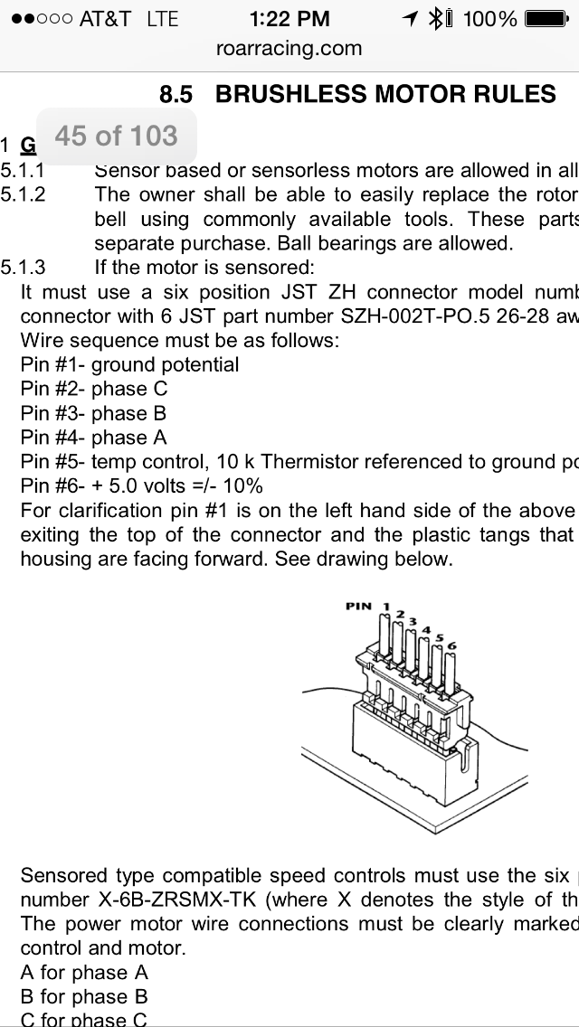
Zoom in on this image of two vescs. The pinouts are lebelled on the sticker for the sensor port, and you can see the orinetation of the connector so you should be able to define them from that.

Sure thx, but my problem is not the connection on the vesc, they are labled good
I´m having trouble finding out the phases on the motors. I can´t tell which one is phase, ground, sensors 1-3 and temp.
Don’t know if it’s the same as Alien Power System motors, but I made a tutorial 9in french) for these motors :
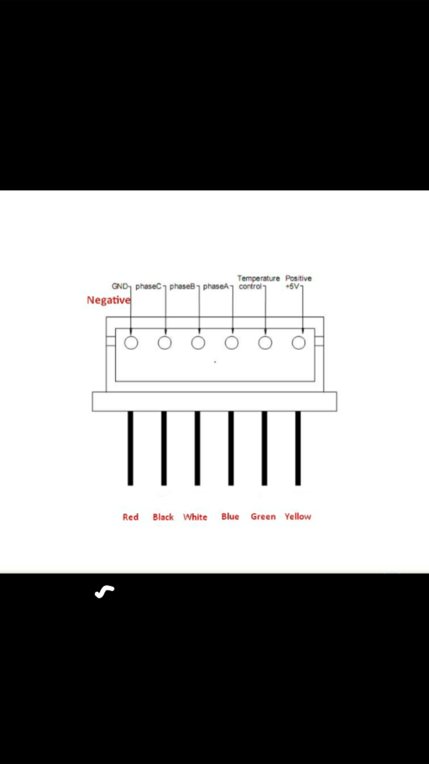
pin # VESC - Description - Motor sensor wire color
1 - 5V - Yellow 2 - Temp sensor - Green 3 - Sensor Hall 1 - Blue 4 - Sensor Hall 2 - White 5 - Sensor Hall 3 - Black 6 - GND - Red
Here is what Bruno (APS) sent me :
Thx for that, but I think it´s a different one. If you compare the colors, they don´t match.
And you can´t really tell from the outside, because the sensor pcb is blank and epoxied to the motor:


Check out my Carbonated build thread.
TL;DR green/blue/yellow = sensors red/black = 5v and GND white = temp
1 Like
Cool! So there is a norm for that, thats good
Alright! Thx for that, makes sense now
