Some of you may have seen @InitialDriveGTR 's flex-sensor based glove controller. The funny thing is, while he was ordering parts for his, I was also gathering parts for mine. I didn’t copy his design and he didn’t copy mine obviously, we both came up with the same thing at the same time.
That being said, he’s way more experienced with arduinos and designing these types of systems and the like, so I’ll definitely be taking some cues from his design
anyway, I finally got some time this weekend (schoolyear almost over!) to start designing my own version of the esk8 glove controller. I don’t wanna crack open my esk8 so I grabbed my quadcopter to use for testing. I’m posting the video (and the code, screenshots, and schematics) below.
tell me what you guys think, or any ideas for improving it as usual
First test: it’s a little jumpy as far as how it gets started, but i think i could code a function that ramps the pwm values up and down more gradually. I’ve also tried putting a 10uF capacitor in parallel with the flex sensor but it seemed to pull the voltage down over time, instead of remaining constant when left alone
also: the reason it’s cutting out near the top rpm is becase the function that generates the pwm value is going over 255, which is the maximum that the pwm function takes, if that makes sense. I have very little coding experience so idk if i’m using the right terminology
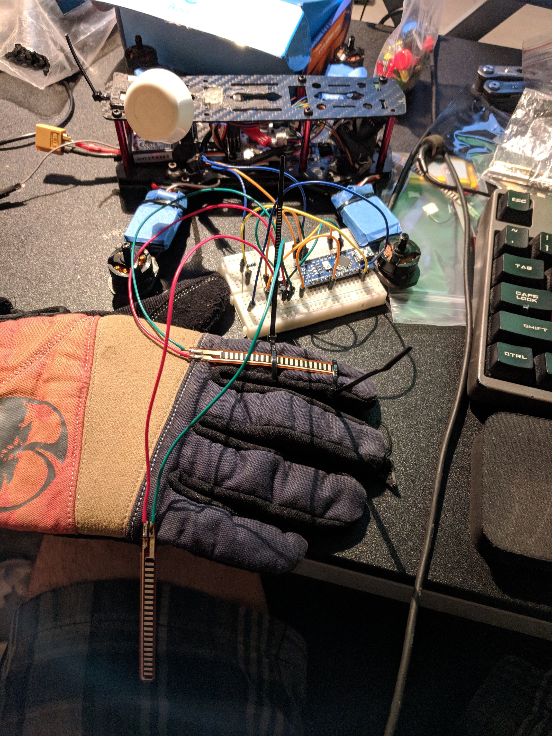
here’s an overhead shot of the breadboard so you can see exactly how it’s set up. Nothing too complicated, just messy because I’m a total noob. the resistor is 100KOhm
yeah, exactly. Probably multiple if i can figure out how to use that for more precision, such as one on my first finger for throttle and one on the pinky for braking
I also have messed with this design. Safety things to consider…
•away to engage/disengage the use of the throttle (ie when not on board or on board when you dont want any type of action to take place)
•fingers will change position when trying to balance out of a situation.
•brakes, dont want them to start braking at an unwanted time either
Possible solutions…
• pressure sensor / built in switch(tactile button)
• using multiple flex resistors for throttle
• tactile button + flex resistor
Main issue is safety “checks and balances” as to not get tossed from your board from sudden acceleration/burst or jumps of or brakes suddenly engaging.
Not trying to discourage you at all. Id love to see what you come up with.
thank you, this is exactly the kind of feedback i was hoping for!
i think i’ll have a dead man’s switch somewhere on the glove, or a small slide switch that turns off throttle control without turning off the glove
I hadn’t thought of that, I’m gonna need to work around it and test a bunch of different solutions to see if it works
i want to put brake controls on my pinky, so two different fingers are involved in the overall throttle control
I’m going to need a lot of different things going on here to prevent injury, but i think the most important thing is that the fail state should either be neutral or a very gentle brake
haha, im in no sense handy with this kind of thing, there is a reason i’m not studying for a major in engineering. So if you do start making these, ill take nine
Last update for tonight. Just got a second sensor wired up and coded it in. I don’t know exactly how I’m gonna handle the two different inputs (should I add them, subtract them, average them? I have no idea) but I’ll have a few days to think about it before I get back to work. One more day of school, then two days of tests.
I’m assuming you’re operating your circuit as a voltage divider, fed into the ADC. I’d bet money you found that the digital value you are getting is operating within a range, and not between 0 and 255 (8bit) or 0 and 1023 (10bit). Of course you can identify your operating range and scale it to fit your output (PWM) which from what I read is 0 - 255. That will linearly sync your measured resistance from fully relaxed to fully flexed to your ESC output.
The downside to using this method is that since you are effectively “zooming” in on a small section of your ADCs measurable range (0v to 5v in the case of your Nano there RIP my two, I fried them two days ago and was forced to change platforms), your output will become very jumpy due to insufficient resolution on your input.
I haven’t looked into the ADC on the Nano very much to see if it even has this, but the proper way to handle a voltage divider based input is to have an ADC with +VRef and -VRef inputs.
On an integrated board such as the Nano, this would mean using up an additional two analog inputs to be used as your VRef inputs, however you would be able to take two trimmer pots (one for the +VRef and the other for the -VRef) and then the ADC channel actually reading the flex sensor, will only measure the voltage range you want.
There are ways to do this completely by potentiometer but its a shitload of tweaking, it’s not very reliable, and there are other drawbacks such as excess power consumption. The E-INK displays I’m using on my design have to be driven with RAM restrictions on the 328 AVRs. I just got two ESP8366’s in today that have only one analog input and that means I can’t directly use one on the glove side of the LCS. Since I’m using SPI as my main communication bus for the radio and display, I figured why not use a 4ch 12bit SPI chip…
Hope this helps you tackle some of the problems I think you may encounter… I have about 20 years of experience building electronic systems so let me know if you need any guidance, I’d be more than happy to help. Two people tackling the same problem is still a 100% increase in efficiency overall.
#2 id look into this guy here “gy-ads1115/ads1015” i use them with ESP8266’s for automation sensors and is all package up in a breakout board. 4ch, Comparative, gain amplifier, I2C, voltage 2.0v-5.5v, addressable up to 4 on a single I2C line.
@InitialDriveGTR … what is the advantage/(your plan) of using ESP8266 vs. NANO or PRO-MINI on the glove remote?
i had crossed this idea a while back with other users but safety checks and balances stopped me from pursuing this and put the project in park till came up with some… and well other projects just took its place, so I’m happy to see the both of you working on this project and am excited to see what you all come up with and maybe “lend a hand” when i can and maybe follow along with a 3rd prototype (since already have all the electronic parts already) as to have extra data numbers/input differences that may arise for tuning the end product.
I saw those ADCs but I ordered the 3204s on my business mouser account I can can also run them at a way higher speed than I2C on HSPI…
I switched to the ESP primarily because with the nano, I have to load graphics into RAM in chunks and send them to the display in sequential packages to build the graphic THEN push the image onto the actual display. Wifh the ESP, I have enough RAM to load a graphic from flash, send, and display all in one shot. All glove related DSP will handled on the glove side of the interface to minimize overhead on the RF link.
thank you, this is exactly the kind of technical response i was hoping for!
yeah, that’s exactly what’s been happening so far. i’ve successfully scaled and mapped the main throttle (i’m only reading from two fingers) but the second one is just returning a weird oscillation that almost looks like it’s reading the pwm output or something. weird.
I wanted to use a voltage divider because i want my final design to be as simple as possible and i planned on replacing the arduino with an ATTiny45, but it looks like my code is gonna end up being too large for its 4KB capacity. c’est la vie i guess.
your response does have some stuff in it I don’t understand (again, highschooler with no real experience in coding or electrical engineering) but that’s perfect because it gives me something to read about in the next few days.
I’m getting really excited about this project, loving all your updates bro


 so let me know if you need any guidance, I’d be more than happy to help. Two people tackling the same problem is still a 100% increase in efficiency overall.