After spending days looking at posts about every topic possible, I have a better idea of how to build my first esk8. The only subject I need help on is the wiring.
So in order to get my head around that topic, I first created a simple wiring diagram:
Nothing complex. I’m planning on using 2 5S batteries with a VESC.
Then, I looked at how to charge batteries, and that’s where it became a bit more complex. If I understand correctly, I either need to buy a battery charger like that thing (https://hobbyking.com/en_us/imax-b6-50w-5a-charger-discharger-1-6-cells-genuine.html) or go the hardest way and setup a BMS and buy a cheap 37V charger to plug-in.
Why not ? Let’s try and do that.
So I looked around and tried to build the next 2 diagrams.
First one is with a BMS for charge and discharge:
The second one is for charge only:
Are those even OK ? Have I made any mistake ?
It’s actually quite hard to find proper information as there’s a ton out there, but I think I got it right.
I’d be happy to fix those diagrams if I made any mistake. As there’s no post about wiring in the FAQ, I was thinking that maybe my post could go in there if it’s any good. My first goal is to learn how to properly wire my setup, but I’m also happy to help any beginners out there. I can also create other diagrams for popular setup if you think it could be of any use (like a dual motor setup for instance).
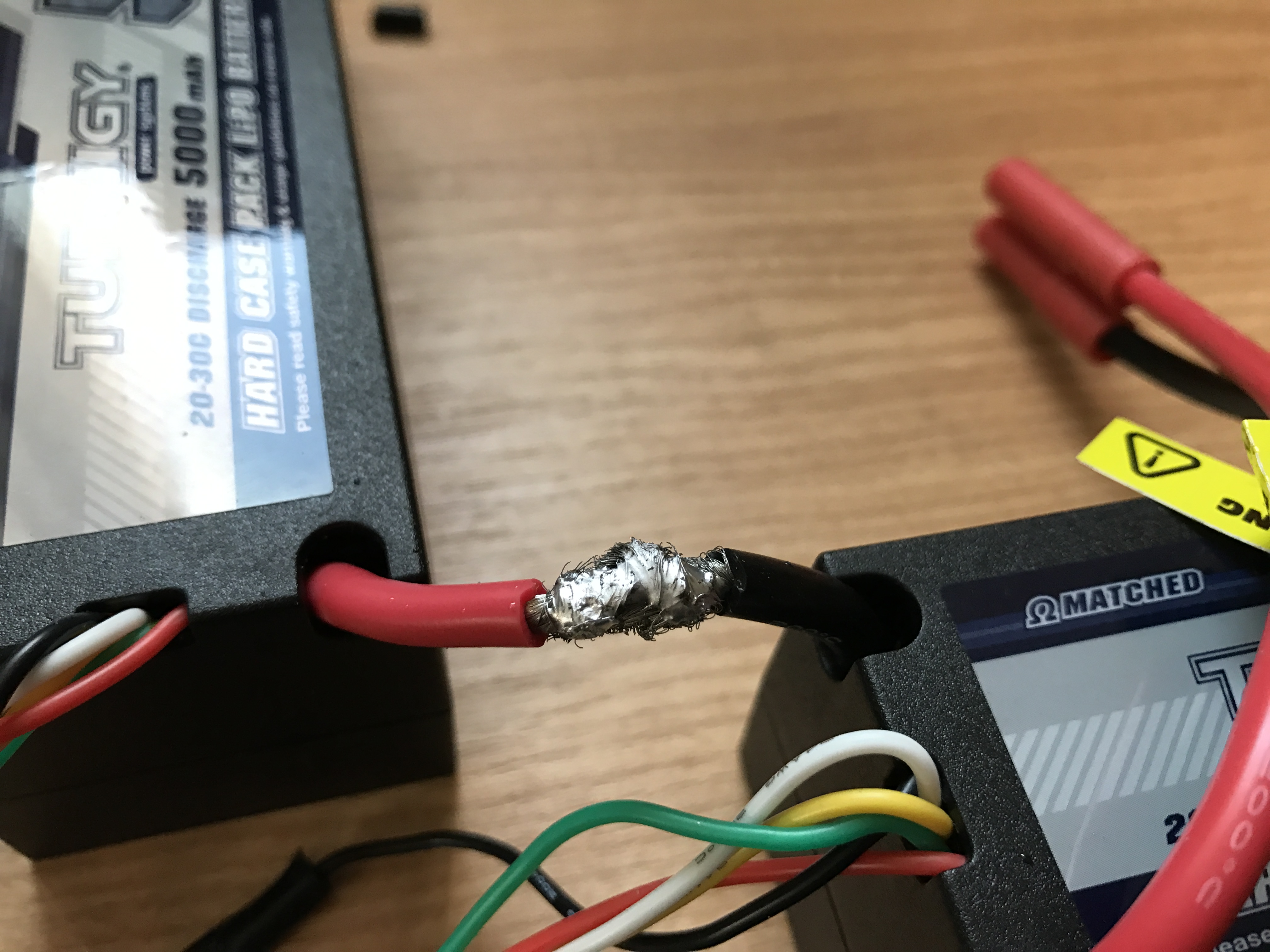
Then yes the battery is wired properly. However, for your charge only diagram, there’s tons of excess splicing which makes the diagram hard to follow. You should directly connect a dedicated charge port wire to the battery positive, a dedicated ESC positive wire to the battery, a dedicated -P charge port wire, etc.
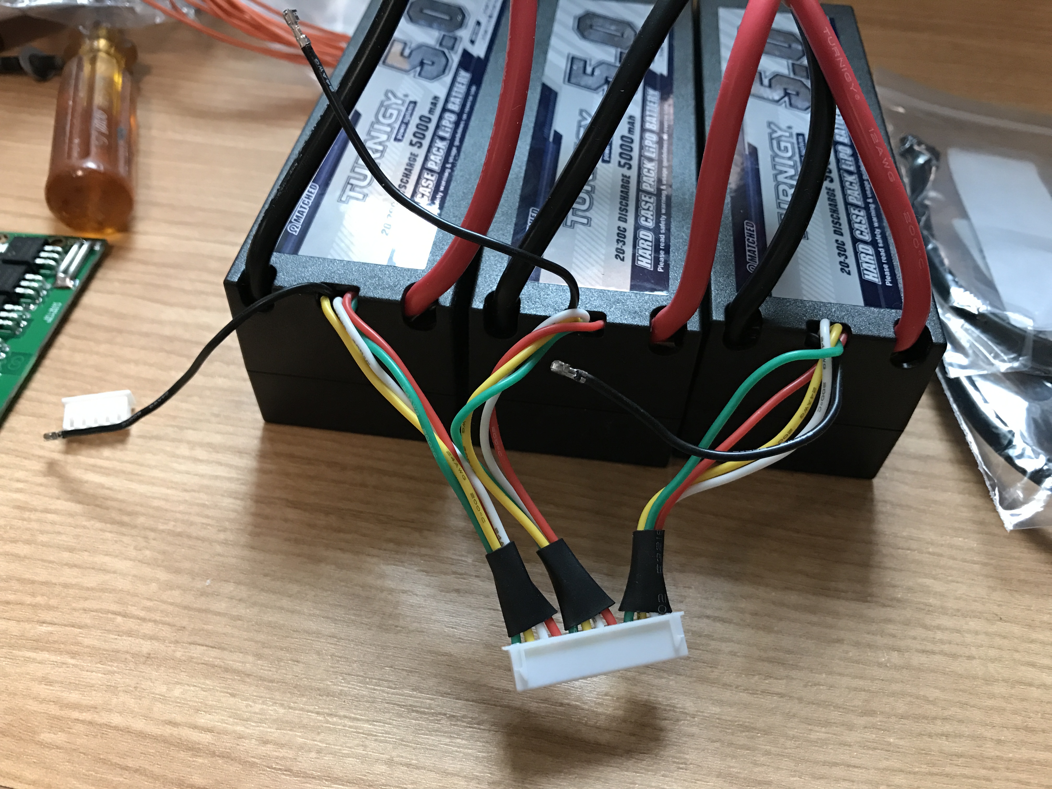
Also I would eliminate the extra set of balance wire connectors, that’s just another point for potential failure. Here’s my LiPo battery pack and how I wired the balance leads to the BMS:
I think I got my charge only diagram right then, I’ll try to make it more readable. Not easy to draw lines in every directions and keep things clear at the same time.
And thanks for the pictures. For coupling your balancing ports all together, it seems that you just removed the pins from each white connector and inserted them all into one connector, right ? Not even soldering required ?
It’s not just the drawing of the diagram, but the actual principle of making every wire ‘dedicated’ and minimizing splicing. Electrically everything works, however future maintenance and upgrades will quickly become a pain in the ass. Everything should be self contained to avoid confusion and easy replacement.
I’m not sure I follow you here.
I tried to make everything modular, so everything can be remove or disabled easily, that’s why I use connectors almost everywhere.
What you say is that I should use less connectors and just solder everything together ?
No I’m saying you should make sure that every connector/wire is connected to the positive/negative terminals of the battery/BMS. Your current diagram shows a ton of splicing off a single battery positive wire.