I just started designing an enclosure for my board using fusion360, i’m new to the program and don’t really know how to move forward with my design.
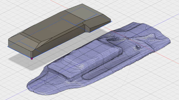
Currently I have a basic design for the enclosure (to fit a 10s3p, BMS and a VESC) and a 3d scan of my deck with the battery sitting on top of it, like so: (scan only consists of about 4/5 of the board)
As you can see above there are side channels on the deck so I cannot just design a flat lip around the entire enclosure because it wont sit on a flat surface.
I was wondering if it was possible to somehow extend the enclosure into the curves of the deck and get a enclosure that is perfectly contoured to the deck. Or similar to cutting a model with a plane instead cutting the model using the scan of the deck.
I’ve searched online but have not found any answers. Does anyone know what search terms would help me find a tutorial or solution for this? Also any other suggestions for a solution are welcome.
So I’ve decided not to drop the enlosure into those side channels but instead, just fill them with some putty or something and just make an enclosure that contours to the shape of the deck.
I’ve got a decent enclosure design but have a really stupid problem, I’m sure it a super simple solution but fusion360 is not letting me make the changes I want to.
Basically I’d like to put a few cutouts on the highlighted face for a battery meter, on off switch, charge port and the 3 motor wires. But for some reason it’s just not working. Anyone know what the problem might be?
I’m not on a computer right now, so this is just off the top of my head.
Model- Sketch-rectangel(or what shape you want to cut out) choose correct plane and draw cut out.
Then right click on the cutout and “push” and push through the model. Select " cut" under operation tab.
Should do it.
Tried doing that doesn’t seem to work. I think it has to do something with the way I modeled it, I think I unnecessarily over complicated the model and sketches and now that face is locked or something. Been trying to figure this out for days, its the last step before I send the file to get printed.
Yeah it can be due to the sketch it wont allow you.
You could try to cut it from either under or over the model. sometimes it helps to change directions.
Finally figured it out, the part was an assembly of two different models. So I just had to make the cuts in the original model and it just updated in the assembly.