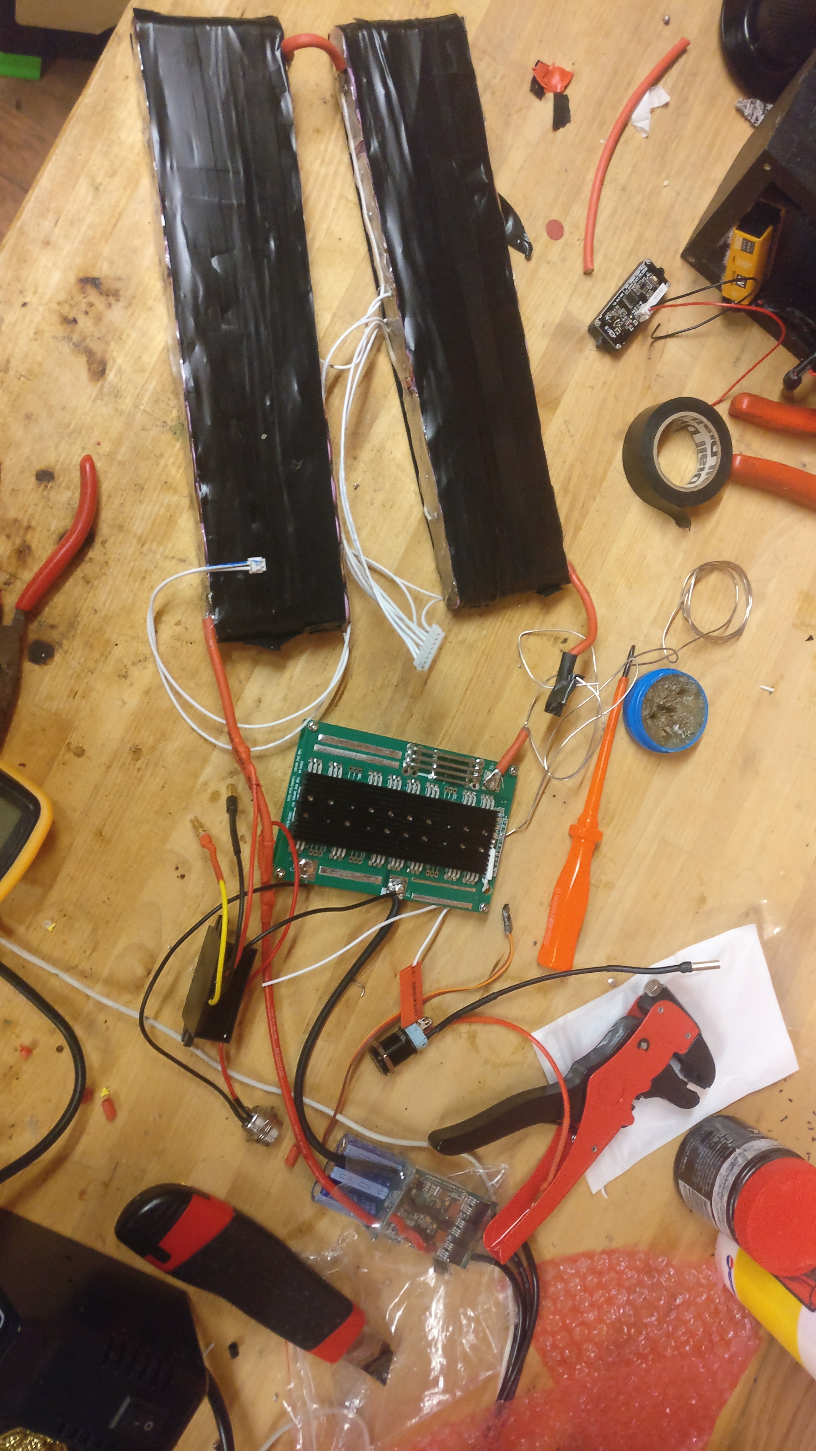
I have finally started building my board. I wired up my board according to a template I found on the forum. I have used a bestech 80 amp BMS with an eswitch and connected it up to a 10s3p 30q pack that I have made. I also have a step down converter that I am using to light up the LED switch.
Everything was wired up with no problems at all, however when I attached the 12v power of the step down converter to the switch, smoke began to arise from the BMS.
I bought the BMS from Alien Power Systems and am thinking of contacting him to see if I can get a warranty replacement.
Here is what it should have been:
E switch wire to C
E switch wire to NO
stepdown converter positive to +
stepdown converter negative to -
None of those pins should be bridged to eachother.
The stepdown converter should be connected to the battery further down the chain from the BMS. The stepdown converter should only turn on once the BMS turns the board on.
The BMS eswitch should NEVER be exposed to external power.
Thank you so much for telling me how to wire it. However the eswitch wasn’t directly connected to the power. The eswitch was connected to the two contacts whilst the step down was connected for the led on the light.
Also, for the two E switch wires which one is connected to wich terminal on the switch?
If you did wire it up like that diagram, then the C would connect to NO when the switch is activated. And C was your 12V and NO was your BMS. So it actually did directly connect them.
It doesn’t matter which BMS wire goes to NO or C. They should be the only two wires that ever connect to NO, NC, or C. In your use you just want to use NO and C.


 As well as wiring the switch like this and bridging the two poles of the switch with one of the eswitch wires
