I can’t answer that since i’m still a little lost, but i highly recommend this book, “Brushless Permanent Magnet Motor Design” by Dueane Hanselman, the good think is that it doesn’t assume you know anything like most books about motor design, it starts in the beginning and explains all the theory behind
2 Likes
So why can the motor current be low if the applied motor voltage is high? Is this the right way to interpret your question?
The short answer is: because of the “Effective voltage”, created by the VESC’s duty cycle and battery voltage is only somewhat higher than the motor’s “BEMF voltage”, which is kV and RPM dependent. “Drive voltage” is the actual potential difference between the “Effective voltage” and “BEMF voltage” and is the actual potential/voltage difference that is pushing electrons through the motor winding.
“Drive voltage” = “Effective voltage” - “BEMF voltage” “Motor current” = “Drive voltage” / “Motor winding resistance”
Example calculation with 100kV motor, with 100mOhm winding resistance. 40 V battery voltage. 25 Amps of motor current @ 0 RPM and 1000 RPM.
0 RPM, BEMF = 0V: “Effective voltage” = “BEMF voltage” + “motor current” * “winding resistance” = 0V + 25 A * 0.1 Ohm = 2.5V “Drive voltage” = “Effective voltage” - “BEMF voltage” = 2.5V - 0V = 2.5V Vesc duty cycle = “Effective voltage” / “Battery voltage” * 100 = 2.5V / 40V * 100 = 6.25% Electric power = “Effective voltage” * “motor current” = 2.5V * 25A = 62.5W
1000 RPM, BEMF = 10V: “Effective voltage” = “BEMF voltage” + “motor current” * “winding resistance” = 10V + 25 A * 0.1 Ohm = 12.5V “Drive voltage” = “Effective voltage” - “BEMF voltage” = 12.5V - 10V = 2.5V Vesc duty cycle = “Effective voltage” / “Battery voltage” * 100 = 12.5V / 40V * 100 = 31.25% Electric power = “Effective voltage” * “motor current” = 12.5V * 25A = 312.5W
Now, provided I didn’t screw up the calculations. You can see that we’re pushing in both example RPMs 25 Amps of motor current, but why? The VESC effective voltage is completely different in the examples, so why is the motor current the same?
Because BEMF voltage.
As the motor spins up, it’s BEMF voltage opposes the effective voltage. What we should look in the examples is the difference between the BEMF voltage and effective voltage, which I would call the Drive voltage, because it’s the actual electron moving potential difference. And as can be seen above, it’s 2.5V at both RPMs, which explains the 25 Amps of motor current.
Thoughts on this model, questions?
2 Likes
I’m saying how can the esc light up when pushing it with no batteries, so a circuit there, but not enough current to blow it unless the brakes go on. (Without batteries talking about). That’s what my question was on the vedder site
Current doesn’t flow without the load.
vESc by itself only demands x load. Which equals to milliamps. How hard is that to understand?
Hook up a 12v led with a resistor, the led load is only a few mA, but the battery can power it for years. Does the led explode? No because the led only demanded x current. Aka load. Same thing.
Without a battery hooked up to the vesc, when the motor spins, the load is the components of the vesc. Spin the motor components demand a small load. Eventually if you spin the motor fast enough the voltage is to high for the system and the components burn because of voltage, not because of current.
Im imagining a generator spinning hooked up to an led and the generator is varying it’s output voltage. How does the led not blow. What limits the output from the generator.
So it will blow if spun fast. Without brakes?
1 Like
Back to what I just said.
The components are rated for x voltage. The buck circuits limit voltage on the each for the different components. So the MCU stmf4 gets it’s 3.3 and 5.5v, the low sides still exist. When the motor spins fast enough to over volt the DRV(63v) then the 5v buck burns the TVS diode(d5) and you have 8v gong to the MCU and they blow in order…
So yes a fast enough motor will over volt and blow the circuit. But within the limits of the circuit they only demand x current because they only equate to x load.
2 Likes
I figured it was something like this is the reason behind the ole “dont ride your board switched off.”
This makes perfect sense.
2 Likes
Well, the same dangers are present even if your board is on. The real question should be, “is your battery connected?”.
Below is an illustration of the “battery - motor controller - motor” connections.
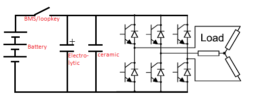
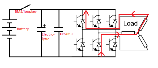
Even if the battery is disconnected from the motor controller, the motor can power it up. Why? BEMF voltage. as the motor turns it generates a voltage on it’s phase wires. Now this voltage is relative to the motor’s kV value and it’s rpm. Let’s say we have a 100kV motor turning at 1000 rpm (going downhill maybe), so it generates 10 V from it’s phase wires. This current will be able to flow back into the DC bus, through the mosfet body diodes and charge up the capacitors, as illustrated below.
The actual DC bus voltage will be the BEMF - 2 * “body diode forward voltage”, so maybe realistically around 8.6 V.
This is enough for the DRV8302 buck regulator to create it’s 5V output and then the 3V3 with the linear regulator and the MCU will power up. That’s the short answer for how the motor alone can power up the motor controller.
The voltage on the DC bus can become high in two cases when powered by the motor.
Either the motor is spinning very fast and therefore generating high BEMF voltage, which is enough to exceed the voltage ratings on the components, making stuff blow up.
Or because the motor is spinning and keeping the motor controller powered up and you don’t realize it, you decide to apply the brake with the remote control. When the motor controller is regen braking, it’s actually acting like a boost regulator for the BEMF and thereby increasing the DC bus voltage. Remember that the motor controller is acting like a buck controller when it’s driving a motor to lower the battery voltage to a more suitable level for the motor. Well in regen braking, it’s behaving like a boost controller. Using the motor BEMF voltage as a source and boosting it above the battery voltage, so the current will start to flow to the battery.
Now why does the motor controller blow up when it doesn’t have the battery connected to it? Because we are boosting the motor’s BEMF voltage, but there is nowhere for the energy to go, except to the DC bus capacitors, but the problem is that they can’t store a lot of energy, so their voltage will keep climbing and climbing very quickly, until the voltage gets so high again that stuff starts exploding.
Did this explain it?
10 Likes

Thanks, I actually had a good conversation about this particular phenomenon with a customer at work, who develop and manufacture BMS’ for industrial use. We’re developing a product for them.
The scenario we were talking about was, what happens if you’re regen braking and your battery pack gets disconnected for a reason or another.
Two things can happen, if your motor controller is fast enough it can detect the dangerously high DC bus voltage (VESC high voltage cut-off) and stop the regen braking, at which point you can’t slow down anymore, because you can’t dumb the energy anywhere, but at least you didn’t blow up your motor controller.
Or your controller isn’t fast enough, it will boost the DC bus voltage too high and blow itself up, at which point
again, you can’t slow down anymore and you blew up your motor controller 
The bleed resistor could prevent this, as talked in the http://www.electric-skateboard.builders/t/diy-break-chopper-protection-against-overvoltage-no-cutoff/49823/34 thread, but depending on it’s location (battery, BMS, motor controller) and the electronic/mechanical fault that happens, it might still not be able to save the day. The best place for it would be at the motor controller, because then even if the battery and the BMS get disconnected, you can dump the energy right at the motor controller.
5 Likes
Dude, I had to read that like 4 times but I definitely gained some insight there; thank you for the knowledge bomb.
So, I got the bulk of this, but to some up (well I am in no place to sum up the eloquence)… the biggest risk is not having the battery connected more than merely the board not being on as there is nowhere to dump the excess BEMF voltage? If the motor controllers are switched off but the battery is connected, will the BEMF voltage still dump the excess into the battery or can it only do that function if it is switched on?
Depends on if your using an antispark with fets or a loop key style… As one can be back powered one cannot.
1 Like
Of course, I get it…Still took me too long to figure out why it mattered… duh and lol. Gracias.
1 Like
Even the anti-spark/BMS might allow current to flow back to the battery from the “load side”, if it’s not a fully blocking FET setup. Loop key is indifferent to the direction of current, as one could guess.
The Vedder anti-spark would not stop this, as the current is able to go through the mosfet’s body diode in the anti-spark itself + through the body diodes in the inverter bridge, in the case that it’s just the purely the motor generating a high BEMF voltage. Not 100% sure what’s the conduction path during regen braking in the mosfets, but regardless vedder anti-spark would still allow the regen braking to happen.

A fully blocking switch setup usually has 2 N-channel mosfets with their Drains connected together, as shown below from the BQ76200’s datasheet. The current would be able to go through the first mosfet’s body diode, but then would be blocked by the second one. The second mosfet would need to be in conducting mode, for the current to go to the battery.

1 Like
I’m revisiting this, as I made a mistake in some of my wordings in regards to top speed.
I’ve been gearing for the top speeds I want to achieve at dead battery. So as the battery dies I won’t really ever notice as it is outside of my normal riding range.
2 Likes
@SimosMCmuffin what is it that makes the motor less efficient when it is producing torque while further from it’s no-load speed?
when further from the no-load speed the back emf will be less but why would that make the motor less efficient?
similarly why would a 100kv motor doing 20mph be more efficient than a 200kv motor doing 20mph? Are motor amps more inefficient than battery amps for some reason?
Well, the further the motor is being run from it’s no-load speed, the more amps you have to give it (hence it’s further from it’s no-load speed), which directly equate to more losses just in the windings due to their resistance. That is a pretty simple fact that should always be true. I think there are then more dynamic losses which are speed dependent.
Then there is the mechanical efficiency perspective, with the electric power IN and mechanical power OUT. for example if we are not driving any load, but we are spinning the motor, then our mechanical efficiency is 0%, because there is no useful mechanical work being done, but we are still using electrical power to just spin the motor.
It’s mainly because of the higher currents with the higher Kv motors. Not so much in the motor itself, but everywhere else. I mean all things being equal in the motor, same stator size, same amount of copper with only the amount of winding turns changing, hence the different Kv values. They should still be able to run identically at different battery voltages, but with the higher Kv motor, the current everywhere else in the electrical system will be higher, so more resistive losses in the wiring and in the transistor stage.
Or so my understanding goes.
EDIT: wiring wise the difference between high and low Kv systems, is the wire insulation breakdown voltage and wire resistance. This goes for the whole electrical system overall. With very high voltages we wouldn’t need as much copper to carry the same power, because low current, but we would need more insulation strength/thickness to stop the insulation from breaking down due to the higher voltage. Opposite of that with low voltages we would need more copper with less insulation to be able to carry the higher current.
I think this makes sense, if you look at something like an electric car with the battery voltages in the multiple hundreds of Volts. They still have pretty thick wires with thick insulation on them, but imagine how much copper (which is expensive) they would need if their system was a low voltage one. I think it’s more economical to have higher voltage, use less expensive copper and more cheap insulation on wires, because the electronics can handle the higher voltages these days.
1 Like
Copper losses should be relatively linear when ignoring skin effect of the windings. However the core losses increase exponentially with higher switching frequencies and flux densities. The magnetic field of any electromagnet tries to resist change thereby introducing a hysteresis in the system and causing losses. At even higher frequencies eddy currents induced in the stator taken an even stronger effect.
Shouldn’t copper losses be on an exponential curve in relation to current? P = I^2 * R ?
1 Like