I figured I’d create a new topic to document my project instead of continuing to hijack the 105mm thread.
I decided to rewind the SkullboardVIP motors since they were so problematic. They are very similar to the Maxfind motors:
24N28P
Maxfind version: 6 turns of 14 strands of .30mm diameter wire (approx. 28.5 gauge), outer wheel diameter 90mm, wye termination, winding scheme AabBCcaABbcCAabBCcaABbcC
Skullboard version: 8 turns of 10 strands of .30mm diameter wire, outer wheel diameter 105mm, wye termination, winding scheme AabBCcaABbcCAabBCcaABbcC

I completed rewiring of 2 motors with:
10 turns of 3 strands of 21AWG, outer wheel diameter 105mm, wye termination, winding scheme A-b-C-a-B-c-;A-b-C-a-B-c-
 Tools used:
192ft. of 21AWG magnet wire
Latex gloves, leather gloves
Magnet wire stripping tool
Heat gun
Jeweler’s screwdriver (flat)
Toothpicks
Plastic credit card cut in half
Short flat square-nose pliers
30-min epoxy
Soldering iron and soldering tools
Heat shrink, various sizes
Tools used:
192ft. of 21AWG magnet wire
Latex gloves, leather gloves
Magnet wire stripping tool
Heat gun
Jeweler’s screwdriver (flat)
Toothpicks
Plastic credit card cut in half
Short flat square-nose pliers
30-min epoxy
Soldering iron and soldering tools
Heat shrink, various sizes
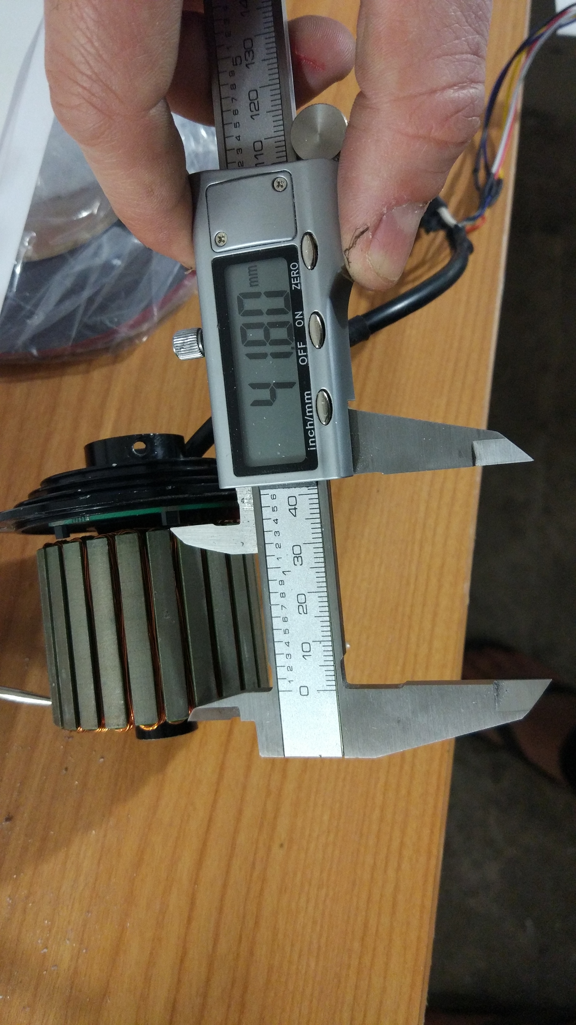
I began by disassembling the motors. Get the stator out of the hub using pressure, not hitting it. It helps to heat the the hub lightly using the heat gun to make it expand some so that the bearings release easier. Unsolder the connectors of the wires coming into the motor after documenting where everything is connected. While wearing leather gloves, heat the sensors until the epoxy softens and either by pulling on the PCB the sensor is attached to or prying it lightly with a sharp flat instrument (I used a jeweler’s screwdriver). Beware, the stator will become quite hot. This is what you’re wearing leather gloves for. Complete releasing all 3 sensors this way so that you can set the PCB aside, along with the plastic guard protecting the wires coming into the motor and the connector itself. Remove the heatshrink protected connection and cut off the soldered part. You’ll need to do this in order to unwind the motor. Begin removing the windings carefully, trying not to damage the green protective covering on the stator. If you examine the windings carefully and remove them in the correct order, this will be quite easy.
Cut all of the segments of wire at one time in order to assure they are all the same length. I cut them at 64" lengths. This left 2-3 inches of wire at the beginning and end of each phase. If you want to simply run the wires (all 6 wire starts) out of the motor and direct to your ESC, account for the additional wire length at this point and make your wire lengths longer.
I began winding the first phase A at the 6th slot CCW from the first sensor position. This became crucial in having enough room for placing the PCB back in and making all the necessary connections later. I completed all windings wearing a latex glove on the winding hand to get better grip for pulling the wires. Start winding from the middle to the outside, complete 4 turns. This will cover the tooth. At the completion of the 4th turn, insert the credit card pieces into each side of the tooth you are winding, and squeeze the ends using the pliers, but gently. This is to flatten the windings without damaging them. On turn 5, you will have 1 wire on the inner part, and 2 on the outer part. If you need to move the windings around, use your nails, or plastic tools.
 For windings 6-8, I found the best way to be stitching the wire into position one strand at a time. It gets tight at the end of turn 8. After completing turn 8, I repeated the squeezing process, but note that getting the cards in is much more difficult now than after turn 4. You only need to squeeze the outer edge of the turns to make room for turns 9 and 10. Starting turn 9, you’ll create a \ on the tooth, so I did that on the side of the stator with the connections going out, as there is more room on this side of the stator. Once turn 10 is complete, you’ll need to jump 2 teeth and start the next winding. Be careful to run the wire as carefully as possible making it look like in the diagram so that its out of the way when you go to wind the next phase. When all phases are complete, use the stripping tool to remove expose the ends of each of the wires. You can now test to ensure none of the wires are shorting out to the stator or to each other. You can now arrange the phase ends where you want them to end up (see completed winding for specifics) so that you can cut them, re-strip the ends the minimum necessary, and solder them together. I soldered the phase ends in 2 bundles. They do not all need to be together in one bundle for the motor to work. I then did the same thing for the matching phases of each half together (A from the first half to A from the second half, etc.). I could not get the connections to fit into the PCB cutouts for the phase ends, so I cut off that portion of the PCB. I then re-glued the sensors into their spots using epoxy and left it overnight to harden.
All that remains is to reconnect the outgoing connector and run it through the provided channel. End result is 113kv


 Completed rewinding, outer connections to be done