Can you elaborate more on the stealing Wh anispark switch?
I haven’t heard this before
Can you elaborate more on the stealing Wh anispark switch?
I haven’t heard this before
let’s call that a trampoline ! awesome job mate.
well, its overexaggerated, but since these mosfests have a higher inner resistance than a 10awg wire, youll have some losses there … and extra heat. its just a handful watts either way.
there are other reasons for me though - I nearly lost one battery because a switch broke and its fallback was “always on”. bad weather, so 1 week later i checked the voltage and I hit 2.5V/cell.
from that day on I save the space, Whs, heat and money for a shitty switch and go hard on/off with a 10awg bullet connector loop key. it sparks, but I havent had any issues with it in 5000km on several boards ![]()
@whitepony I have several builds with switch, breakers, loop key and or electric switch. Loop key anti spark is the best! They didnt brake under water. Consume no energy. Cut off charges for sure. No current limits. They just rock solid. More important with a proper placement and a cable, it could be transformed into deadmans switch.
Yeah, I learned this lesson myself, simplest solutions are the best, I will try AS150 connector loop key in my eMTB (initially wanted XT90AS, but it seems… to small for my trampa)
Have you considered a extra switch alongside your bullet connector with a resistor so you don’t get a spark. I say that because I’ve lost a esc just connecting a battery, probably bad for capacitors. I was also thinking like a momentary switch that you press with your pinky while connecting the bullet connectors
after I melted an xt90S once, I also decided against these kind of solutions - brute force simple, screw the spark, i have yet to loose an esc from switching on/off. maybe i start thinking different about it once that happens to me. until then im with @squad : simple wins! 
Can you post a pic of your best loop key setup?
Thanks for all the info! Your posts have been a huge help with my builds
only board left is my diy deck with the direct laminate, so its a little, uehm, off?
anyway, picture shows “on”, left and right port is charging ±, left and mid is on/off!
The simplest solutions are always the best and most elegant! Love the low profile of the bullet connectors compared to XT90’s 
Thats crazy awesome. How does that work? Is there a diagram for that somewhere?
You’re not afraid of accidentally shorting those connectors? They look awfully close and exposed. Maybe I just don’t fully understand what’s going on here. 
made one now - its a basic loop key setup:
well, there is SOME thinking in these connectors by now ![]() first of all: they are enclosed in 1.5mm thick glued shrink tube thats really indestructible and hard to get off. this sits in sugru (partly seen on outside, mostly on the inside), which is an awesome non conducting and quite robust material. so nope, not afraid at all that something just wears out and shorts ultimately.
first of all: they are enclosed in 1.5mm thick glued shrink tube thats really indestructible and hard to get off. this sits in sugru (partly seen on outside, mostly on the inside), which is an awesome non conducting and quite robust material. so nope, not afraid at all that something just wears out and shorts ultimately.
the rest of safety comes with the layout itself: if you check my picture vs diagram, it doesnt match, because the diagram was a lot easier to draw like this. the key (hah) difference is: left connector in my boards picture is battery “+” connection. right port on my picture is battery “-” charging connection. if these 2 touch, there will indeeed be a lot of smoke and tears. i designed the charging wire to evaporate instead of anything else, so its easy to replace should that ever happen!
you switch on the board by connecting middle (vesc “+”) and left (battery “+”). if middle (vesc “+”) and right (battery charging “-”) touches, nothing happens at all.
if middle (vesc “+”) and left (battery “+”) touches, the board is on.
so either way, nothing bad happens except for when the 2 outer ports touch - which isquite unlikely! you can see, this is different in my awkward diagram, where neighbor mid left shorts the battery. THATS bad design cause it might happen on accident or so. i just drew it like that for simpliciy sake.
hope its more clear now ![]()
Thanks for the detailed response. So elegantly simple. Since you don’t seem to be using a bms, what kind of charger do you use, and how do you avoid overcharging and keep them balanced?
i explained that so many times in so many different threads 
this thread is a good starting point for charger, nobms & co. it quickly derailed into something else and I think you can stop reading esrly on in the thread. gotta run off to work now 
Damn, you just HAD to link to the ONE thread I HAVEN’T read on this forum.  Thanks for that. I would have never found that.
/thread derailing
Thanks for that. I would have never found that.
/thread derailing
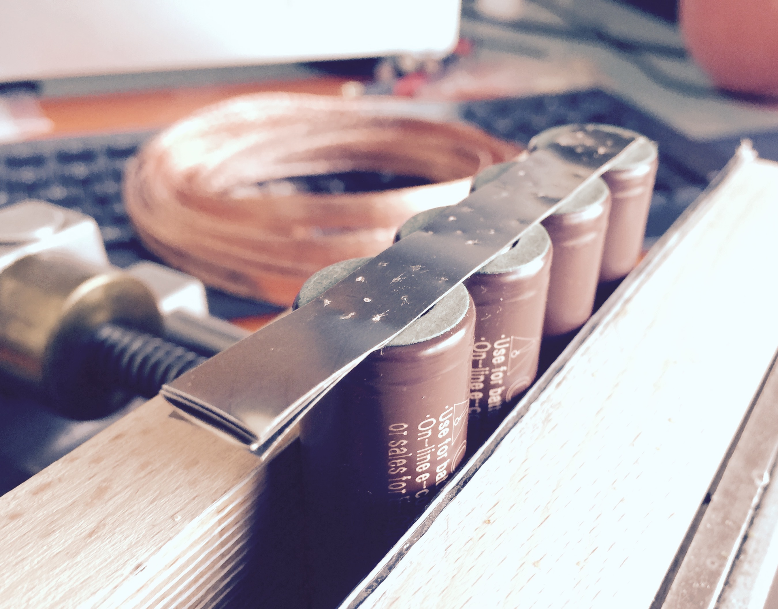
today I made the segmented battery - was a lot of work cause I used 8 nickel strips for each 4P1S pack - 4 strips per serial connections. its a lot more work than just soldering some copper wires ontop of one nickel strip, but it looks cleaner and feels more solid as a pack.
few pictures of the progress:
added cardboard stickers for additional safety @ plus poles
4 layers of nickel strips to account for the max of 80A continuous current
its pretty thick in sum and has a nice solid feel to it
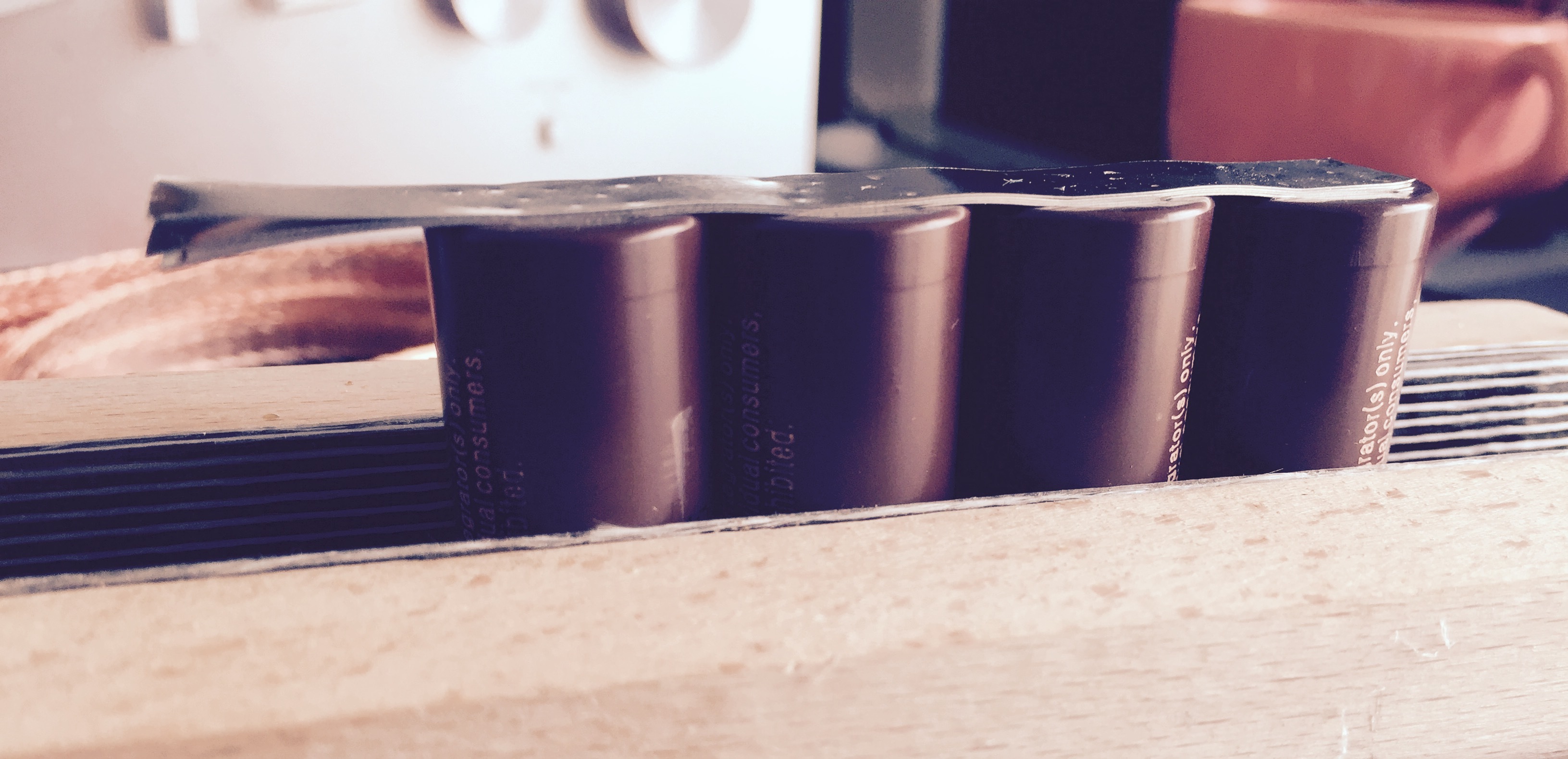
one 1S4P pack with nickel strips extending beyond the pack for the segment connections:
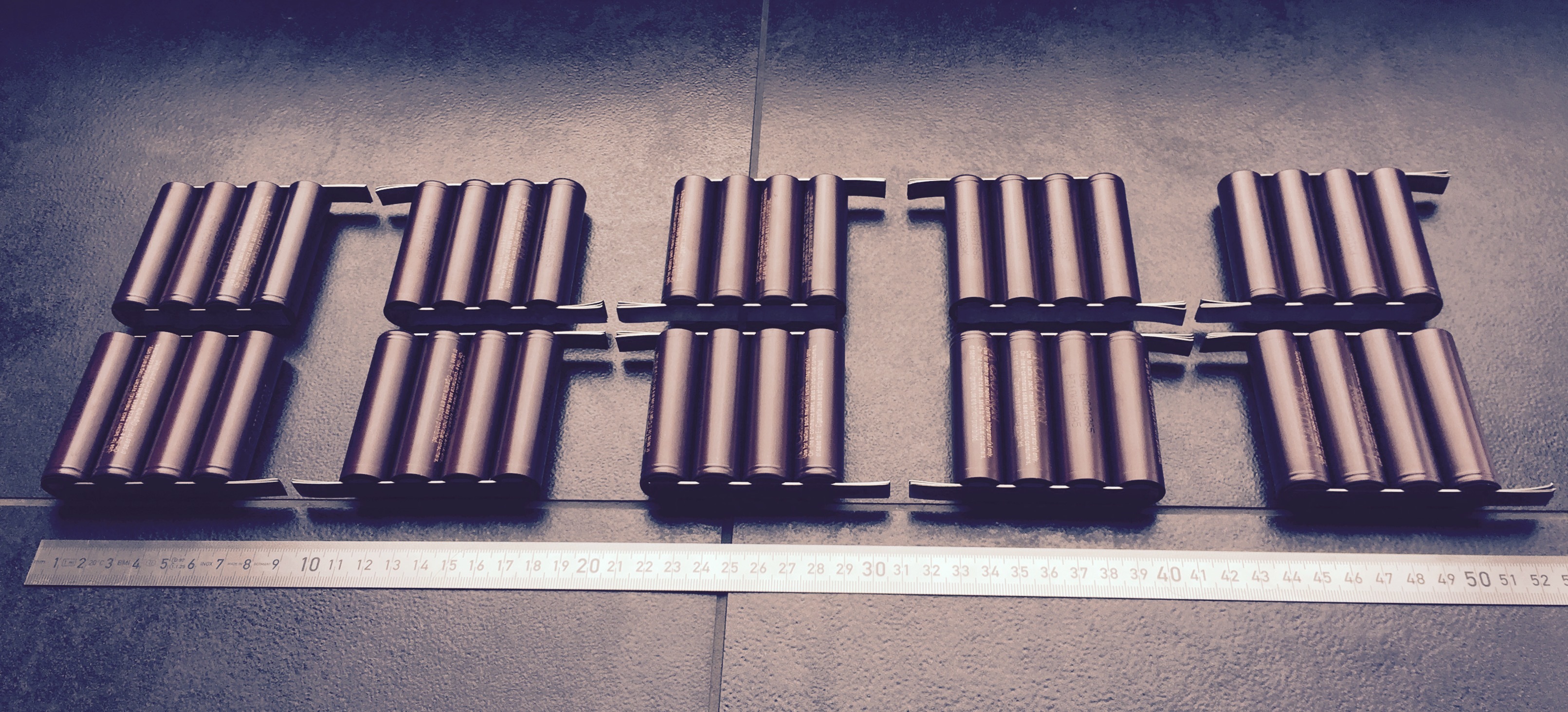
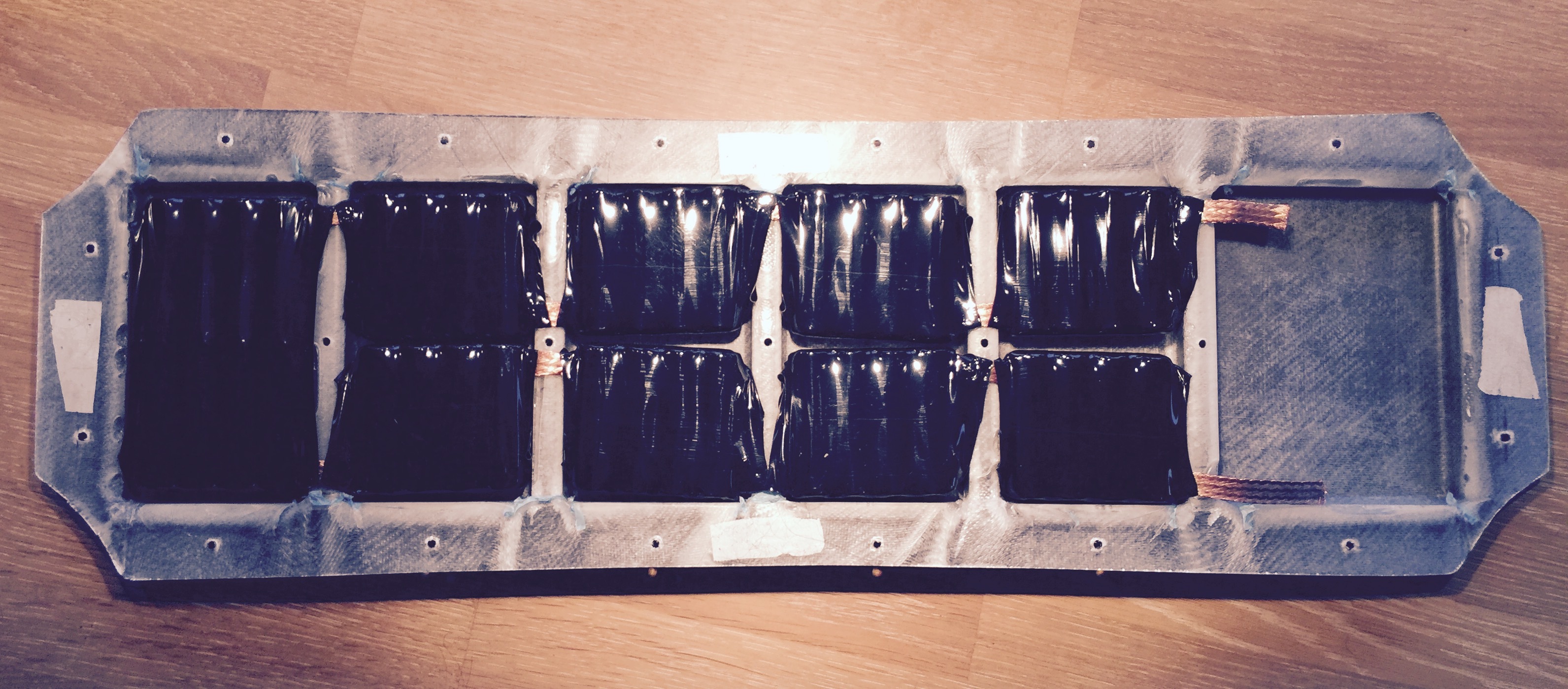
all 10 packs done
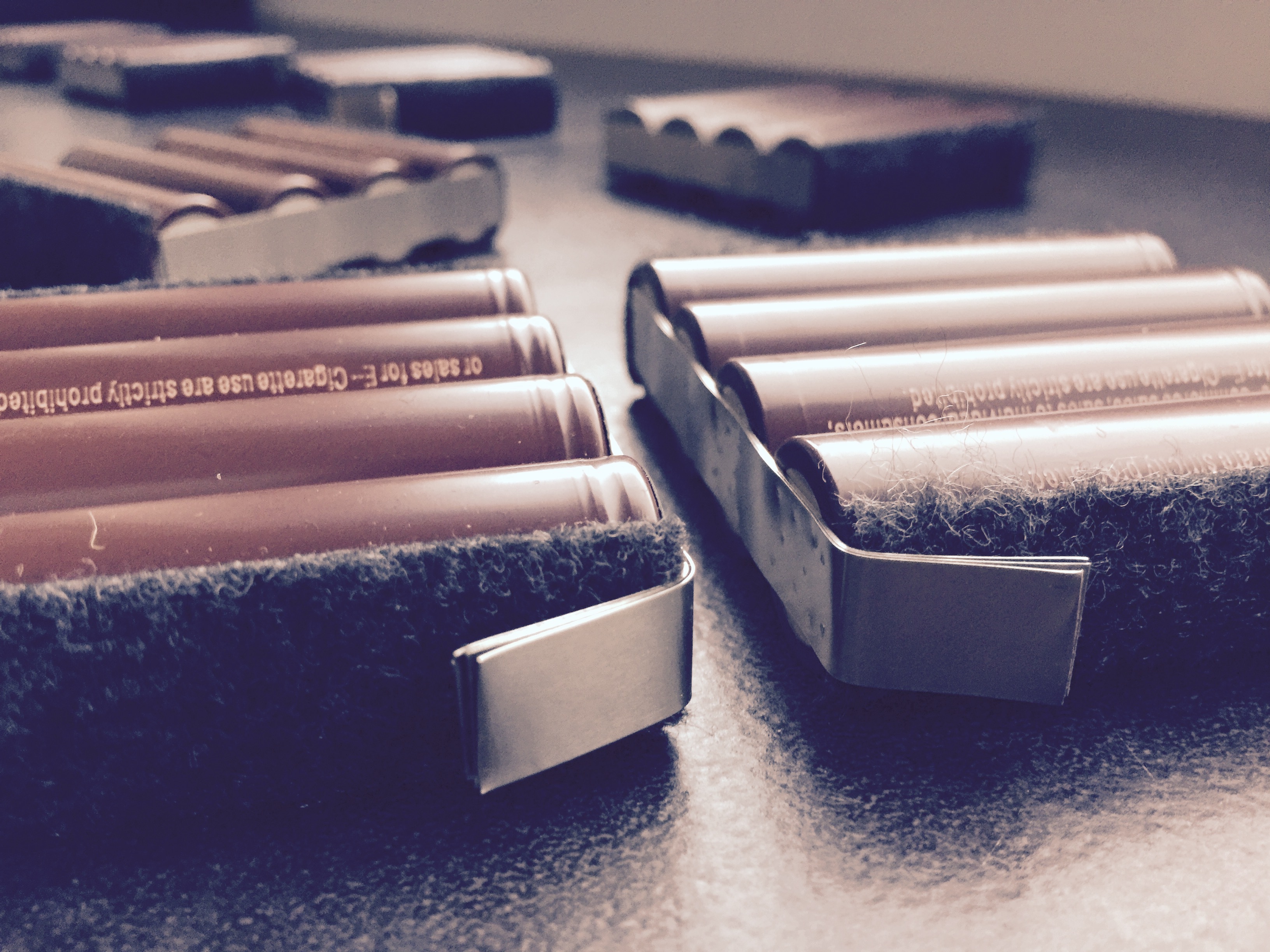
since i want to bend the extension of the strips by 90°, I glued adhesive felt sheets on the cells to protect them from the sharp nickel strips
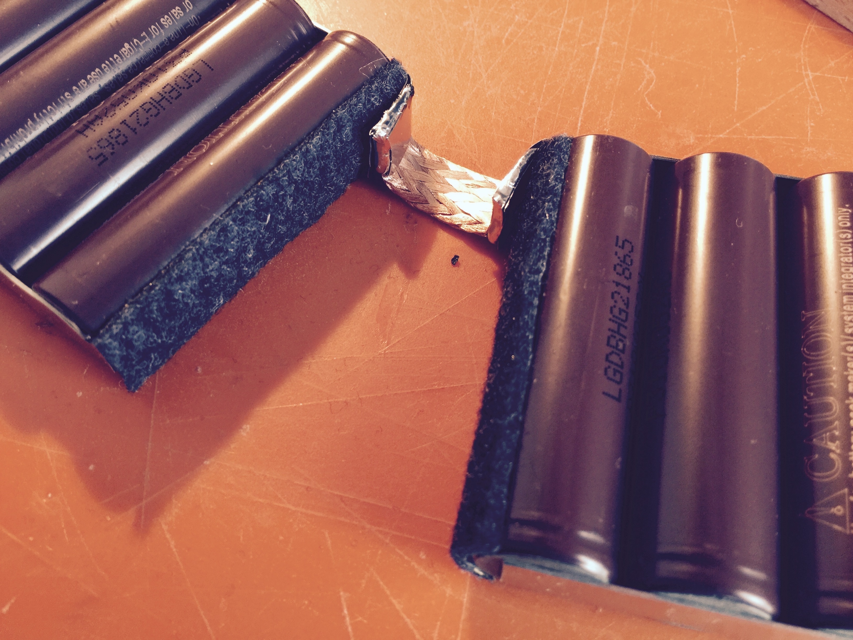
now I started soldering the segment connections with superthick braided copper wire (about 10mm wide, 2mm thick):
did that for all aaaaand done. at the enclosure segments where the braided copper wire is running, Ill dremel some resin out to seat the connections flush with the enclosure base:
finally adding some shrink tube - and I was quite generous - just heated it up and pressed the segments into the enclosure - shrink tube easily gave in where it had to and stiffed up when it cooled down:
waiting for my 2 german vescs & mini remote now - all thats left is adding on/off/charging and 6 phase wire connections to the enclosure. think Ill do that tomorrow!
This has to be my favorite build right now…you are truly inspiring me to build something similar…so clean and bad ass!
The idea of the flex flat wire is pretty clever. I’m going to borrow it for my urban carver build which I’m planing to work on in a couple of months once I get the funds.
There is going to be a good flexiness on the flat wire part, but how are you going to avoid flexiness on each group of 4 cells in order to avoid the strips from braking? Even though there are 4 nickel strips there’s no guarantee those won’t brake as the board flexes 300 times a day.
an enclosure segment does not really flex, only the flat segment interconnections. thats due to the design of the enclosure! even if the board might flex a little in those segment areas, the enclosure will not. worst case the bending board will lift off the enclosure slighty by applying pressure to the 2 middle cells - but the trampa has tons of camber. some mild pressure will only build up after it bends beyond the “flat” point.