
This is my circuit design. I’m sorry that it isn’t in the schematic format, this was just easier for me to read. If you can’t tell what is happening: all of the wires from the batteries are being put into reverse Parallel connectors, splitting it into 4 positive wires and 4 grounds. 2 positives and 2 grounds are being hooked up to a series circuit that powers the VESC, while the others connect to a Parallel connector, which connects the 2 positives together and the 2 negatives. The balance ports for each Battery are connected via a parallel balance board, then are fed to right next to the charging port so I can keep all the batteries in an enclosure with port holes. I would love any critiques that could make this efficient or stop it from blowing up if I did something VERY wrong! I hope that once this is finalized it would be a great starting point for other first time electric skateboard builders.

The whole goal was to make a 12s system so I could get 44.4 volts out of it, and have Parallel charging because of its simplicity. I want to keep it in the enclosure so charging wouldn’t require Battery removal. It’s basically a mix of the two: the charging system is Parallel, while the motor system is series for those extra volts.
I understand what you’re trying to accomplish. But you’re gonna need a switch to disconnect the series connection when charging, then disconnect the parallel when discharging. You can’t have them in series and in parallel at the same time.
The moment you hook up the wires, your lipos will go boom. You’re essentially shorting them out if you hook it up this way.
It’s good I posted this before I did it…
Ah nevermind, I followed the wrong wire on the diagram.
@Jinra No you are right, big boom.
The parallel conections shorts out because of the series connection

@Esrapp21 this is doable but as @DilatedPupils stated you need to disconnect the series connection when the batteries are charging or as @Jinra stated you will promptly need new batteries - and likely a new house. The easiest way I found to doing this was to place an XT90-S key in my series connection so that the circuit to run the motor is off while charging
Example (diagram is not mine):

Thanks for the advice. Boy am I glad now I posted this before I got the parts 
The best way to accomplish what you want is with an onboard 12s BMS and a simple charger.
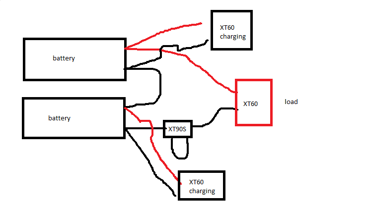
okay to help esrapp 21 a bit i made a diagram wen u ride u plug in the xt90 as(antie spark) and if u charge plug the xt90 out and the xt60 in and the balance connecter if have any question plz contact me
dual bl = dual balance lead (12s)
I would suggest to move the XT90-S loop key to another position. Maybe between one battery and the esc instead of between both batteries.
When you will charge it like your diagramm everything will works. The only downside is that you power the esc becauce you get positive from the upper battery and negative of the “downer” battery. It will not destroy your esc but i do not know the longterm side effects.
dont they have a on and of switch at least my one and his first diagram 2 and if u move it u wil shortcircuit no body likes that
I assume you will use a parallel board to charge both batteries at once.
When you are charging both batteries at once you will have a positive wire (upper battery) and a negative wire (downer battery) that goes to the ESC. when you charge both batteries at once you will have power on both cables even if the loop key is detached. –> The energy comes from the charger not the batteries but this energy goes into the esc and power it on with your current wiring.
here is is fix for no switch users
u can make the xt60 a xt 90 antie spark but this way u need a different key to nulock more thief protection
This would work if he wasn’t trying to charge in parallel. @mountainboardlover69 has the right diagram. Maybe switch the xt90s and the added xt60
Lol… His new diagramm is correct too but the additional XT60 is not neccessary when you reposition the xt90s.
In my diagramm there are two black xt60. these can be wired in parallel (like he did in his wiring). I was just too lazy to draw it…