

7 Likes
Looks really good and compact!
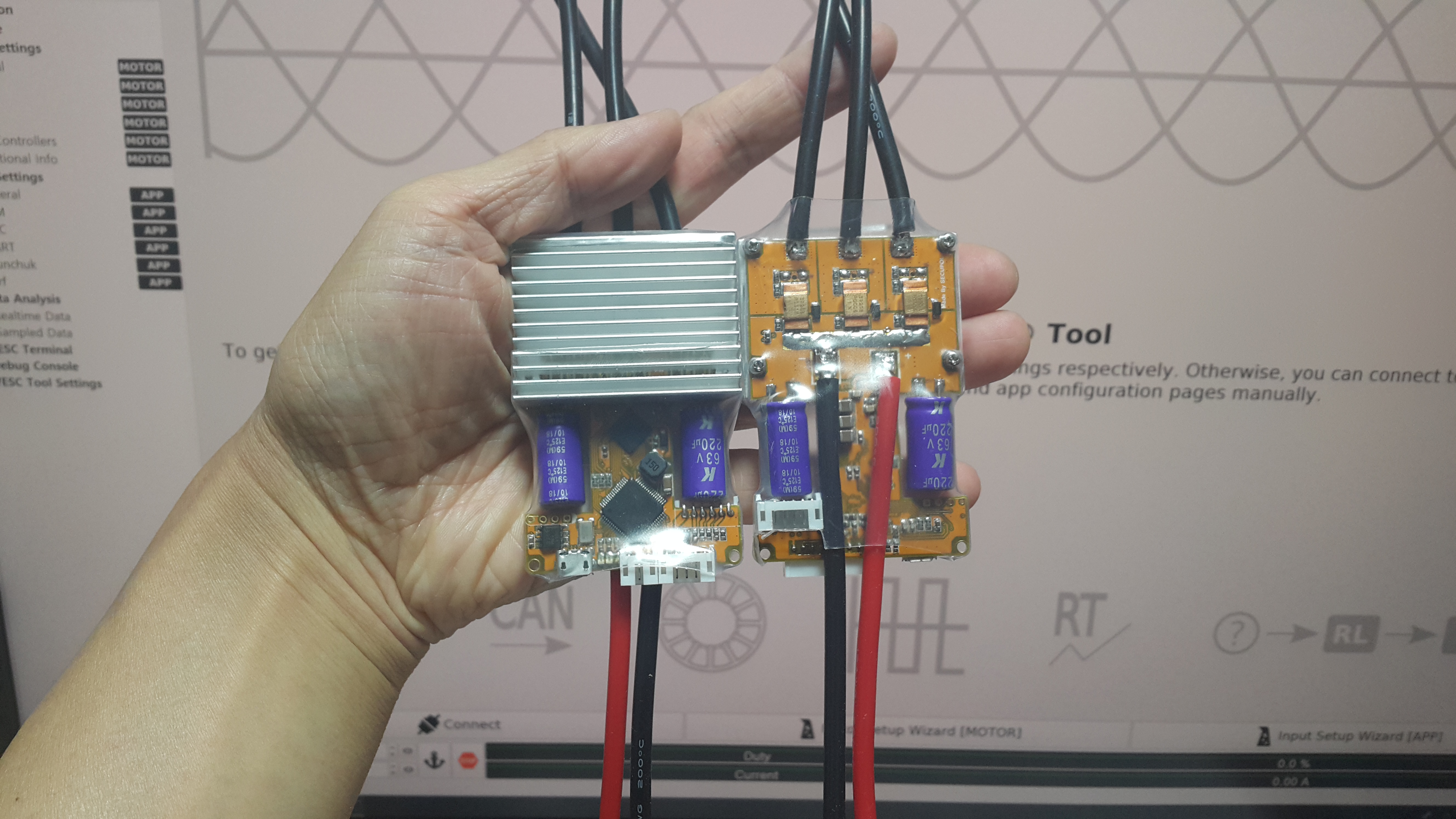
I see that you use three ground phase shunts, that mean that you have adopted the firmware to support them. Could you shine some light on this? Also do you notice any performance difference with the in phase shut measuring that the VESC6 is doing?
The firmware and hardware are almost identical to VESC 6. It’s just a different gate driver for MOSFET.
1 Like
Which one are you using? And is it better in some sense?
What are the rated absolute maximum voltage limits for the gate driver?
It is used DRV8323RS made by TI.
1 Like
Maximum voltage is 60V
1 Like
So still 10S max reliable, 12S for skates that don’t have to be mission-critical dependable, and 13S for daredevils
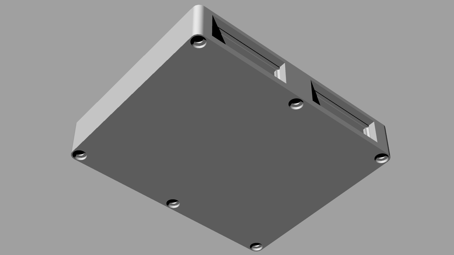
Single Housing(W x L x H) : 52 x 84 x 17 mm Dual Housing(W x L x H) : 102 x 84 x 17 mm PCB Size (W x L x H) : 46 x 70 x 1.2 mm


4 Likes
So this vesc6 will only do 10s?
The same like every other vesc 4 and 6 we have here at the moment
3 Likes
The VESC 7 is 75V, the rest are all 60V but those are absolute maximum hardware ratings and you should never approach those.
5 Likes
I assume you feel the same way about the Unity, would the
Breaking Resistor
RHEOSTATIC BRAKE module SAMPLE PRICE $30
 Rheostatic Brake.jpg889x557 26.3 KB
Battery: <=12s Operation voltage: 57V Startup time: 200ms Max current: 5A Function: when brake reverse voltage is higher than operation voltage, Rheostatic Brake starts working and reduces the reverse voltage to protect ESCs.
change how you feel about the Unitys reliability with hard breaking on 12s? Or do you see it as unnecessary
You should never run an inductive load above about 75% of rated hardware voltage-- and especially on a square wave PWM digital drive.
Using any breaking resistor is not recommended because broken resistors only add ballast weight. A braking resistor system might help but I still wouldn’t do it. I doubt 200ms is fast enough because it’s the inductive kickback millisecond spikes that are the problem. It definitely doesn’t hurt though… you could in theory soak up anything under 200ms with caps.
But there’s no reason to reduce the reliability and add failure modes by edging that close to physical hardware limits with an inductive load fed by square waves. Not when you can just run it at 10S and make a beast esk8 that blows away any commercial prebuilt on the market and is reliable.
The braking resistor is awesome if you live or work on top of a big hill. Could be a lifesaver.
4 Likes
Alright so I shouldnt even bother with 12s 
10s Here I come i guess 
A lot of folks use 12S on these, but I can’t agree with them. For a “toy” maybe but for a “tool” 12S doesn’t make sense with the 60V gate drivers like VESC 4-6
Prepare for 37 folks to say “I did it, and it’s fine” and remember the whole time that lots of people survive car wrecks but that doesn’t make them safe.
6 Likes
First! 10 char
Edit: at the risk of sounding like I agree with 10s, that is sound logic!
1 Like
I usually take my angle grinder and saw one group in half. That way I have 11.5S. Its abit safer, I promise.
2 Likes
Wouldn’t 4 diodes in series with the charge port accomplish the same thing 
Just that then the BMS would never get to “balance” mode
1 Like
You’re beeing too practical about this!
1 Like