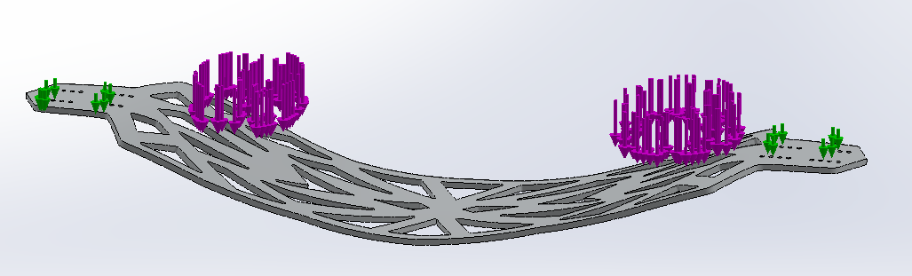
Trying to run analysis of the force from jumping onto a longboard. Adding fixed geometry on the board where the trucks would be holds the ends flat in their original plane, unrealistic to what actually happens. Does anyone know how to allow the trucks’s plane to angle?
I could design a trucks quickly and attach them which potentially could help.
Would you be able to add some bare bones trucks to the deck so that you have the location for the axle and have them grounded to that axis (or ground the axle with a rotational joint connecting the axle to the rest of that baseplate? (running the fea on the assembly with the trucks joined to the deck)
You need a way to tell it what rotational axis the end board would be flexing around…
(I’m running off of Autodesk Inventor’s terminology for this so… lol)
1 Like
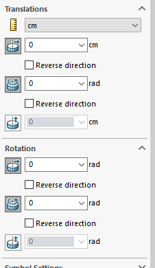
That makes sense. I’m given the option to have it be a roller/slider and a hinge. Hinges require circles to rotate around, bringing me to attaching a truck and fixing the axle as a hinge. Not sure if I’d then need to also define the trucks to be a roller/slider to move along that plane. I’ll do some testing and report back.
Sounds like you just wouldnt need to define roller/slide bc you would only want it to rotate on one axis like a hinge?
1 Like
True, but I also don’t want to encourage elongation along the material. I want to give the trucks the ability to move inwards and outwards.
2 Likes
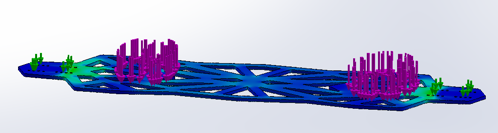
 One truck assembly down, one more to go.
The screw holes in the board didn’t end up matching the trucks after putting some 10-32 bolts through them, so I gave up the idea of using screws and just locked the truck to the deck.
Edit: The other side has the screw holes matching up… weird
One truck assembly down, one more to go.
The screw holes in the board didn’t end up matching the trucks after putting some 10-32 bolts through them, so I gave up the idea of using screws and just locked the truck to the deck.
Edit: The other side has the screw holes matching up… weird
By modelling the trucks you’re adding a lot of calcs to the simulation but it isn’t the results of the trucks that you’re interested in. Best to model them as simple blocks imo.
Depending on what SW license you are using you can then set the blocks as ‘rigid’ which will treat them as infinitely stiff making convergence easier/quicker.
I did something similar a few months ago for my board but couldn’t get a good material to use. What are you using?
Again, depending on your license you might have access to more advanced fixings like virtual wall and remote torque. I wonder if the virtual wall on one truck axle would allow the trucks to get closer together preventing elongation.
At the end of the day, it’s only a simulation, nothing compares to real world testing! Try not to get too sucked into it!
Given the option to let the axle rotate and translate, but unsure if that only means changing the radius of the circle. I’ll test this out too.
@MonkeyM Using a student license. I’ll be cutting a 1’x4’x.25" sheet of 7075-T6 aluminum I have with a water jet cutter.
1 Like
7075 T6, nice! Honeycomb the middle?!
I don’t have the full FEA package so I don’t think I have access to any more functions than you. Let me know if you think I can help with anything though.
This may be the answer:
Edit: Nope, “This solid mass cannot be converted to a beam”
What if you design a very rigid and simplistic truck (no bushings), basically a hanger fixed to a baseplate and constrain the hanger axle on one side as radially fixed but allow rotation and on the other side leave the truck unconstrained in translation and rotation. Such that you pin constrain the axle rather than the deck itself?
Going to try that. A simple block with an axle through it 
Thats what I was originally thinking lol You went into way more detail, NICE!
1 Like
")