I’ve been trying to flash my empty VESC in SWD mode but ST Link utility couldn’t find the target. It appeared that the ST Link wasn’t powering the board. So I decided to add an external +5v supply but the power supply locked itself because of shortcut
If I test with a multimeter the resistance betweeen GND and +5v I first have continuity (0 ohms) and then the resistance raise up to 14.23kOhms in 2-3s.
I guess it’s not a normal behavior, but unfortunatly I don’t know where to search the solution. Would you have any idea of what to check ?
And do you know why the SWD wirering seems to not power the board ? (the 3v line is not shor cutted).
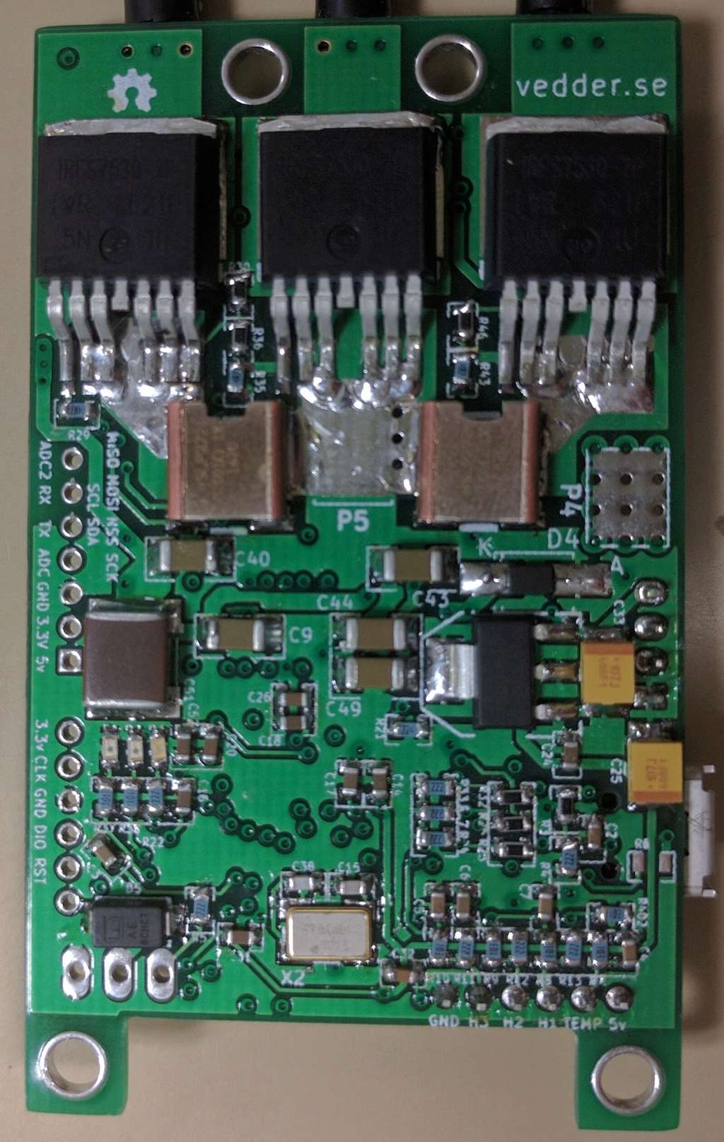
Yes I soldered it myself. I used a “soufflette” in french, a tool which blow hot air. I first added some tin on both the pcb and the TC2117, then I placed the part and soldered the 4 angle pins. Finally I used the “soufflette” to melt the tin under it. I’m not 100% sure it worked, but I couldn’t do other way…
I’ll try to test is this afternoon with the motor, I’ll tell you if it works
new update, I’ve almost finished my vesc. Today I soldered the caps and tried the board on +15v lab power supply. However it locked itself (due to high amp consumption) and I saw some smoke coming from the board…
When I power it up with 5v, everything is ok. But if I increase the voltage the current consumption raise up immediatly.
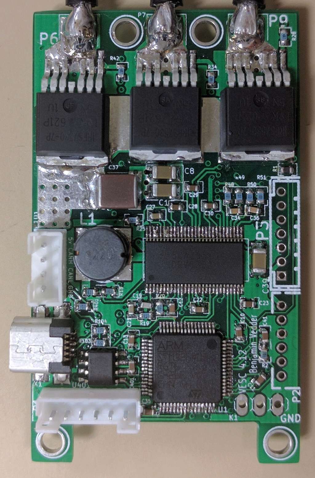
The 3v3 regulator works fine but it seems that the 5v line if shorted with the Vbattery.
I checked the circuit on kicad and I saw that the mosfet driver was driving the 5v. Knowing that I did soldered D5 in the wrong way the first time and for some time the board has consumed 2 amps, do you think the mosfet driver is dead ?
If you need more info just let me know
Thanks…
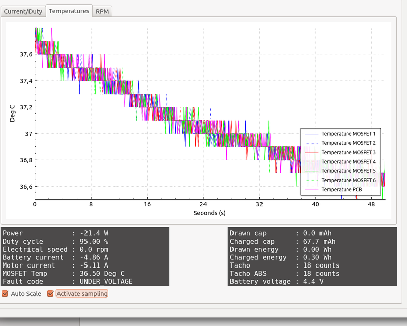
[Édit] Here some data from bldc tool, strange values. Also the chip and MOSFET get quite hot…