EDIT: Looks like the temperature reading was was off (113C when idle) and that was causing the vesc to not want to spin the motor. Bumping up the mofset max temp made it spin but this isn’t really a fix since i have no idea what the actual temperature of the chip is. It looks like a hardware defect with the VESC, shouldn’t be too hard to fix and they offered to replace it so I’ll probably go with one of those two options.
Hi!
Sorry if you see these all the time (I’m sure that’s the case given how many of these threads I’ve read and still couldn’t fix my issue).
I have my VESC set at pretty standard settings. Just changed the battery cutoff start to 33V (which is way lower than my current voltage of 38V on my 10s4p battery). I tried running it with both the stock and Ackmaniac firmwares and had the same results (it’s the hw4.12 vesc from diyelectricskateboards). My motor is a 192kv 6374 turnigy sk3 if that makes any difference. Tried various minimum erpms. Not sure what’s wrong, when I run motor detection, the motor doesn’t even react, it just sits there and after a few seconds outputs a detection failed message.
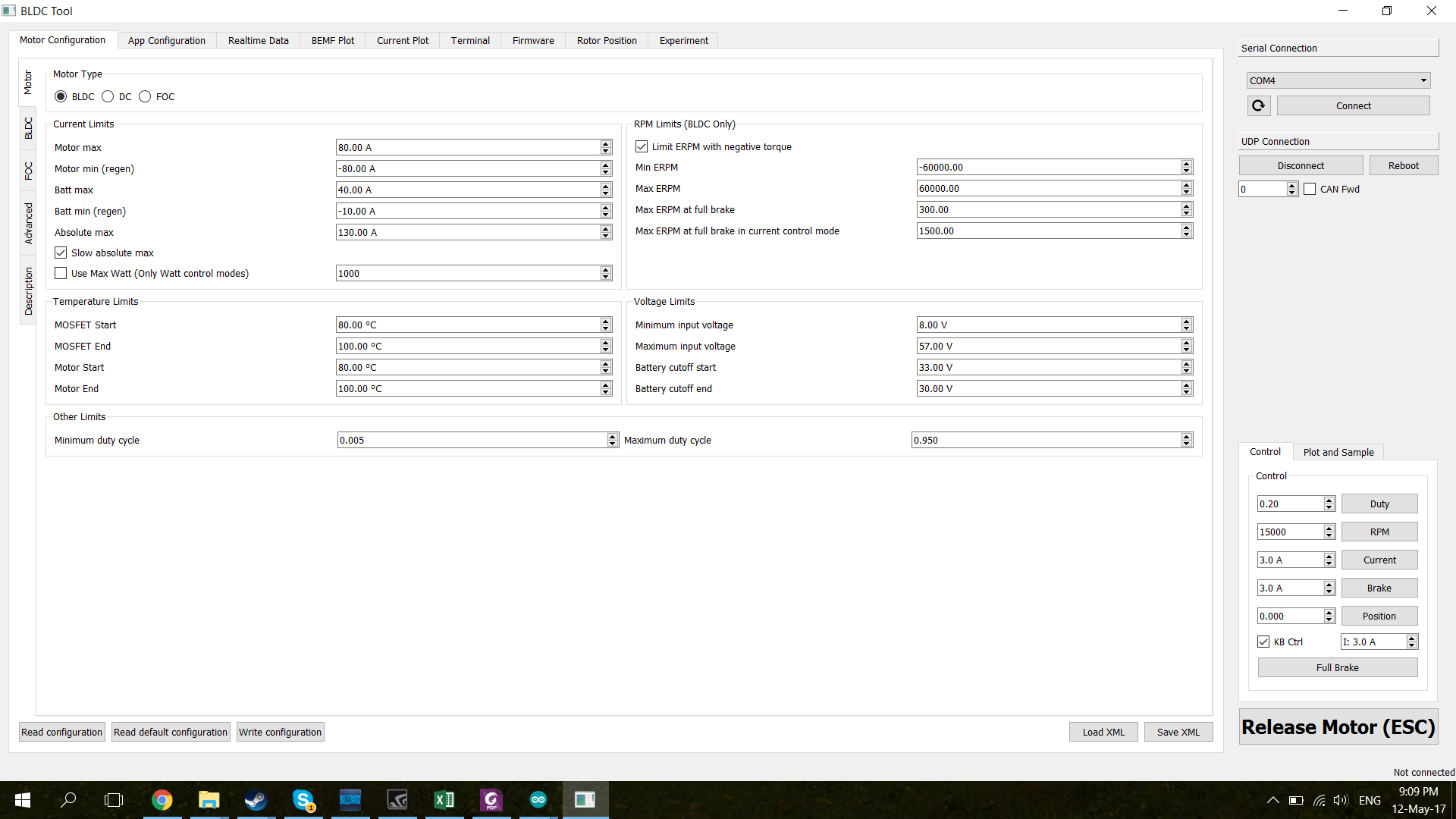
I’m using this config and I can see the motor spinning in realtime data (when I spin it with my hand) so the connection is probably good enough for it to at least try to spin it up:
On your current limits i would start with 60, -60, 60, -30 ams adjust from there after your running
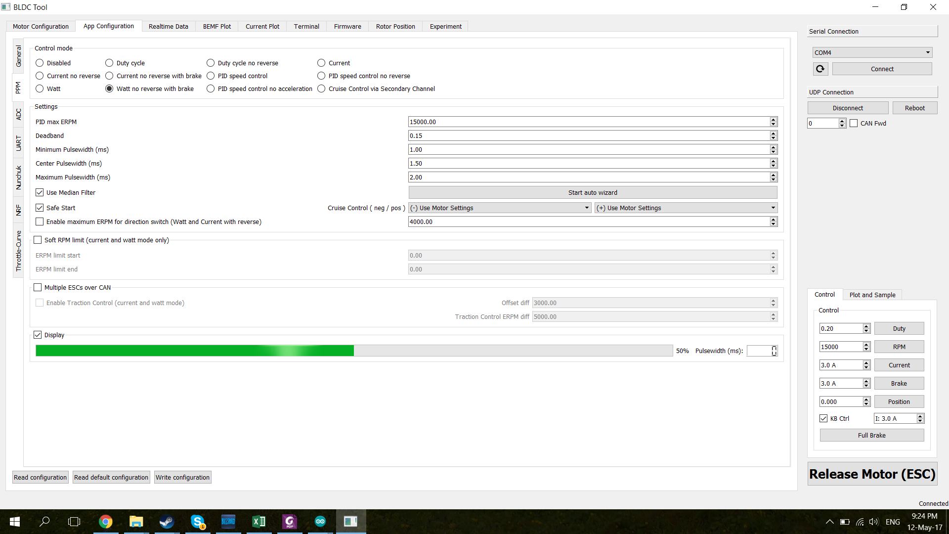
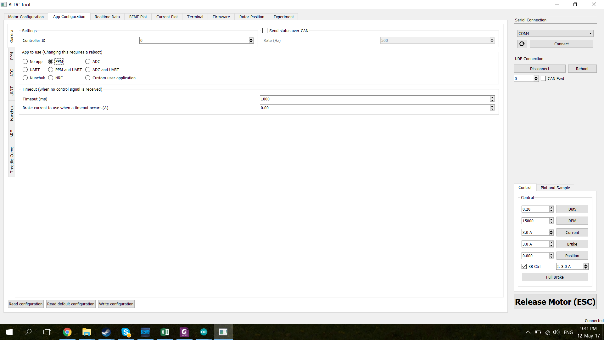
Have you setup PPM yet? Go to app > general and select PPM and click write. The got to app > PPM and select watt/current no reverse with brake and click write.
I just set it to 60,-60,30,-30 (my motor is 80 though, but I guess that won’t hurt it in any case).
PWM was set up, and I could see it change (can’t find a receiver, I’m still waiting for it to get here so I’m using an arduino instead, but the pwm reading was varying which means it should work).
Still not spinning though. I’m not quite sure what’s wrong. Can’t see changes in pulsewidth anymore with the new firmware/software, but even with the motor detection nothing happens.
Just because the PPM signal moves doesn’t mean that your Arduino is working. With my remote off and the RX unplugged it still bounces a little. Can you move the motor using the arrow keys? Look at the @Ackmaniac firmware, gives a lot more options and a ton of explanations. Double check the PPM is selected in app > general. Do a read when on that tab.
Edit: I see you are running the @Ackmaniac firmware, carry on.
Just found a controller-receiver combo. I can make it vary from 1ms to 2ms which does display on the PPM tab. Can’t see keyboard controls anywhere on the BLDC tab.
EDIT2: Changed that and it worked. Really wierd my read mofset temps are so high. They’re not even hot to touch. Is this something I can fix in software? Maybe recalibrate it?
I’m just using my finger to feel if it’s hot and there’s a thick layer of heat shrink on there but it’s definitely not 113C. Is this something that has to be calibrated?
I really don’t know, never had that problem across a dozen VESCs. If your using a 3s or 4s battery to power the VESC that might cause weird shit, at least is has for some people in the past. I would see if you can contact diy support via the chat bubble on the website, or ask @torqueboards here.
@torqueboards is this something I have to return my VESC for or is there some conversion factor I can use to set my max temps (since I assume it was just the wrong kind of thermistor giving the software the wrong value?)
EDIT: Also @mmaner thank you for the help. Took a long time to notice that value especially since it’s half cut off on that page.
@torqueboards I sent an email and a replacement would probably be the safest solution. Is there any way I could know what the issue with the R1 thermistor was and if it would be possible to simply change the max temp in software to take into account the different resistance of the thermistor? Or do you simply recommend not using this VESC at all? Everything else seemed to be working fine and I would be fine keeping this VESC if this is something I can fix on my end.
Thanks for the reply, I’ll probably RMA it but would you happen to know what NTC thermistor was used on that batch?
EDIT:
After looking at the datasheet on mouser it looks like you used the 1kohm thermistors (assuming that was the only error, if you have the part number I’d love to know to make sure, as I said everything else seems ok and this can likely be fixed in software), which means I should be able to find the temperatures that the software will see for the temperatures I actually want. This also makes sense since the temperature seen by the software is higher than the actual temp and my values fall right about where they should.
I’m working on a spreadsheet and will report back (not testing it, but I’m fairly confident this should work without replacing the resistor).
Ok calculator is done but the resistance value seems funny. If you can give me the exact part name I can find the temperature characteristics value B and that should give me the correct values. I’ll stay on the conservative side since it won’t be as accurate but it should work:
I can post this once I test it out but I don’t want to be the reason other people fry their vescs haha.
In any case I’ll set it to something low (maybe an actual limit of 70C), but also current limited since it’ll probably be fine temperature wise as long as I’m below 50A (my limit is set to 40A right now).