Thanks buddy, appreciated!! I think I’ll go with the low discharge BMS as my VESCs are protecting my batts from unwanted discharge effects.
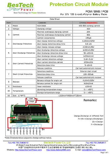
This is the BMS I’ve chosen although Lucy from BesTech recommended getting the same BMS only with 20S Balance lids. Is that seems logical?
Do you mean she recomended a bms for a pack of 20s? Or a bms with 20 pins? Maybe they are extra pins for other things. Did you explain it was meant for a 10s2p and not for a pack of 20 cells? This are the only reasons i can imagine for the confusion. If you have 20 cells in series you WILL get up to 84V and blow the vesc.
Any way the bms you post is perfectly fine. You can even use discharge protection depending on your does power draw and vesc configuration
I’ve tried to explain that I’ve 2 10SP1 packs in parallel, but as I understand you cannot balance 20 cells in which 10 are in parallel though I don’t understand why. I trust you that it is safe to parallel balance the two packs in pairs, so I’ll get one of those and hope for the best. Maybe I could plug them in series just for charging, but that seems complicated.
I am also trying to use a cheap bms for my 10s lipo pack. I want to use your wiring diagram to bypass the discharge. Before I start working on it could you tell how this battery bms set up work out.
Thank you.
I have ended up not bypassing BMS. Try to search forum for bypassing, you’ll find a lot of diagrams which will help.
Mine Worked out fine, with bms on discharge 
I made an error and didn’t pay attention to balancing wires and didn’t connect them in order and burned my bms. So that’s important
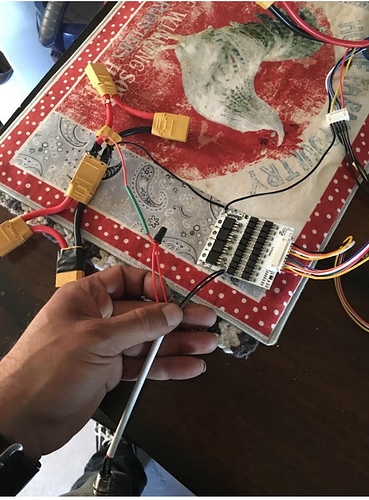
Need help. Using only for charging. I believe I did everything correct but once I plugged the charger into the port, a spark happened on the charging port socket and the charger socket. I have the negative of the battery connected to the B- also with the last balance cable.Also advoiding the red wire on my negative battery. CH- connect to the negative charging port and the positive battery connected to the positive charging port. I didn’t connected anything to the P- because I believe that’s only for discharging What could had happened ? I notice my charging port has 2 negative and 2 positive as well

If we wire it using the alternative you have provided will the bms drain the battery? If i have a esc that has a on/off button and wire it to bypass the discharge will it also drian the battery?
Theoretically a decent bms shouldn’t discharge the battery faster than the battery’s own self discharge. If you bypass discharge that means you are connecting your esc directly to battery. In that case you need some sort of disconnect or your esc WILL dangerously discharge the battery
Just to be clear. I’m not saying the on/off on an esc won’t do. I’m saying it will do only if it fully cuts off power instead off putting it in a stand by mode.
I however will always recommend prying a xt90s loop key somewhere even if you never use it. Just in case the rest fails and you have to quickly turn it off
Hi! I’m bringing this topic back because I’m thinking of doing a big pack of Lipos and would like some advices. After reading many topics, this one seems to be the more apropriate.
I have 9 Lipo batteries 4s 5,8Ah 60C (10 AWG wires). Curently running 3 in serie at a time. (other batteries in backpack).The switch I’m using to turn the board on is a loop key. I would like to make a big pack, include a BMS and connect all balance leads correctly together. (using this would be the best).
The pack in the end would be a 12s 17,4Ah 60C pack. The reason I’m doing that is to be able to increase values of battery current max and max regen on VESC tool. Running on dual, considering only 20% of the 60C (for safety), it would allow me to set batt max to (17,4*12)/2 =104. And considering a 2C charging, batt max regen could be set at 17,4.
As I don’t know a lot of BMSs, I would like to know if you can recommend me one that would fit my needs.
Any other recomendations that you think important before going into this? Wire gauge? Let me now if I have been unclear somewhere.
Nobody? Actually Lipo BMS are not everywhere… And for now I will probably do without…
Can at least someone help me with wire gauge? Since my ESC is wired with 8AWG silicone wire, there is no reason to go lower. Do I need to make my series harnesses 8AWG too?
I have seen many different charts about wire gauge, and I’m not sure on what the size depends…Wire quality, lenght, (but here it’s not really long), Amps? Volts? Power?
Ok, sorry to ask questions that are easy to find… For people that wonder same questions, here is turnigy silicone wires chart:
And for more explanations about what matters to choose wire gauge, here is a well detailed topic about why only current does matter. (as it defines your voltage drop)


