THE ODYSSEY - Single 6374 | 10s3p 25r | SPLIT ENCLOSURE | Custom Improved VESC | Swappable Batteries with SINGLE BMS

Hey guys, I’ve been reading and commenting this forum a lot lately, but nobody has seen any build from me. That’s because i still don’t have one. The reason for that is simply group buys. I’m broke as hell, 16 years old without any experience with diy electronics, so i wanted to spend the least possible.

On october 2016 I opened a thread asking for help about parts to buy. I ended up buying everything except VESC and motor mount from Ajaynagra’s group buy. As you all know, that didn’t go too well, and I had to wait from october to the 20th of April to finally get what I had ordered. That’s why I consider this build kind of an Odyssey :cold_sweat: Here’s the list

  • 190kv 6374 sensored motor
  • 90mm 75A black flywheels clones
  • 15t-36t old pulley kit, tb style with bolts
  • Benchwheel remote
  • Black caliber clones trucks
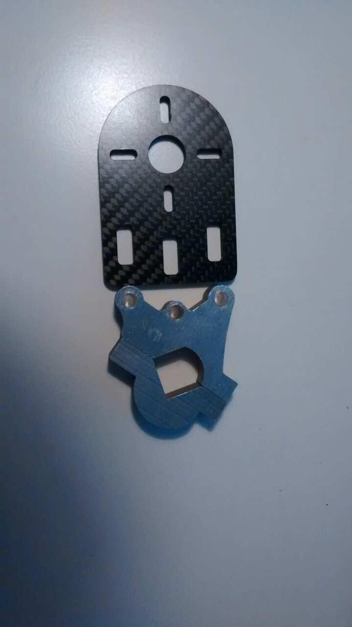
  • Alluminum and carbon fiber motor mount from @fedestanco’s group buy some months ago. Very similar to Enertion’s

  • Vesc from @B4Me, this also was an endless group buy, but way more relaxed since nobody paid anything yet (6 months from the start, but no problems). It should be improved following chaka’s instructions, and I asked him to add an xt90 connector and 4mm bullets for the motor, so that I didn’t have to solder stuff (he’s way better than me for sure)

And here’s a photo to keep you happy, low quality but I’ll get some better ones soon

And here come the problems

  • 10s3p Samsung 25R in compact layout (2 lines of 8 batteries on the bottom and 7 on top like this)

This is not my photo, just an example. Haven’t removed the heatshrink yet.

  • 10s 77A BMS

I expected the battery to come already connected to the BMS with a switch, voltmeter, xt90 connector but seems like my request to put the BMS on the side to keep the battery as compact and stealth as possible got misunderstood. So now I find myself having to connect a BMS without any info or knowledge, I don’t even own a soldering iron. Does anybody have schematics about that BMS wiring? And can you recommend me a good soldering iron, and suppliers for wires and connectors in Europe?

If that wasn’t enough, Ajay didn’t send me the belts I had paid for, so I’m missing 12mm HDT5 belts as well. If anybody has extras, please tell me before i spend 10 euros for a single one in a local store.

Another thing is: I need some good bearings, can you suggest me some good cheap ones (under 30e) I can find in Europe, possibly on Amazon IT/DE?

One more thing is: the deck is flexy I knew that from the start, that’s why i wanted to make a split enclosures build, like boosted. This wouldn’t be a problem, if the BMS wasn’t so huge. I will post pictures tomorrow with the stuff laying on the deck.

Here’s the board

Any suggestion or recommendation is welcome, thanks :slight_smile:

5 Likes

What I did to understand the batteries and how i was gonna wire my balance connectors was making a diagram on how they were all connected(on a premade one before I made my own pack). This was probably one of the things along with looking at peoples setups and diagrams om the forum that made me understand how I was gonna wire mine aswell.

Ended up fine! - And soldering iron I cant give you any direct suggestions since I got mine from local stores, but I highly doubt you’d have to put much money into it for connections as that. Soldering is quite easy, just takes some practice, you can do that on other stuff before moving onto the battery as you wanna do it quick to reduce the heat transfered to battery, Now you dont have to solder directly into the battery but more between the serial connections so in that way you avoid some of the heat. Should be no problem. Just be well informed/prepared before you start :slight_smile:

On the flex part - I had the same issue. Im now running 2 enclosures - split(10s4p). Works fine really. No signs of tear on anything inside or enclosures. You can check my thread out on my board, there is some image with my flex.

You can get a lot of inspiration and info here:

The balance wires from the BMS have to be connected to each of the 10 cell groups. It is an easy job. You dont have to use very much solder as the balance wires is VERY thin.

I would suggest you buy a Weller soldering iron. They are a well known and very common soldering iron which is available almost anywhere. You should get a high wattage iron so you can heat up the solder as fast as possible and therefore transferring as little heat to the batteries as possible. A 60w iron or higher seems to be the recommendation.

If you have any more questions you are welcome to tag me :slight_smile:

This is the wiring diagram that helped me the most: https://www.electric-skateboard.builders/t/help-with-charge-only-bms-wiring/5626/43

1 Like

Where are you located? I’ll send you a belt for free if you pay the postage. :slight_smile:

I’m in Italy

Shipping is 3 euro as untracked letter. Send me a pm if you’re interested

Bearings i´d take are Bones Red.

Thanks for the bearings, i was looking at those but i wasn’t sure. Reviews say these are as good, and cost a fraction. Has anyone tried them? Layout problem:

BMS is HUGE and I don’t know where tu put it. Is it a problem to put it with vesc in the other enclosure? I would just have to pass the wires all together in the middle, and then cover with some braided stuff

And since I now have to solder a bunch of stuff, I think I’m going to add a step down converter and connect a USB port and maybe some leds. Would this be good enough? http://www.ebay.com/itm/DC-DC-LM2596-power-Supply-Buck-Converter-step-down-module-GM-/262136732989?hash=item3d08911d3d:g:XoYAAOSw6dNWSu3o And how would I connect it?

1 Like

And would this https://www.amazon.it/Saldatore-Kit-Topop-220V-Saldatura/dp/B01HYVQRMW/ref=sr_1_1?s=electronics&ie=UTF8&qid=1492797362&sr=1-1&keywords=saldatore work well enough? I don’t wanna spend too much on it

That actually looks OK. Otherwise i would advice to invest in a really good öron, it’s just not a tool i could live without so might aswell have a good one.

As long as it does what it says atleast, but my Italian is a bit rusty :wink:

Otherwise you could check out a Metcal…

Other nice things to have, leaded solder! And helping hands and last flux.

Oh also, the stepdown is really simple. Just ± on the input, same as tour vesc, then ± on output to USB. Check and double check pinout and voltage, there is a pot for setting output voltage on the converter. I would also suggest getting a small usb voltage and current meter!! Its in the same price point, 1 or 2 €, and plugging that in will show if you wired the socket properly… A better sacrifice than your phone!

1 Like

Soo I’ve been thinking about it lately and came out with an idea. Since the BMS is so huge, i won’t put it in the same enclosure of the battery. It will be separated from the battery, and the balance cables will be extended with some of these while the main 10awg wires will just have an xt90 connector. This way, I will be able to even buy another battery, balance charge it and discharge through the bms without having to buy another bms. Little shematic

1 Like

Christ, that BMS is huge. You could just mount the trucks and wheel to the bms instead of using a deck :frowning:

2 Likes

Yeah I din’t expect that :sweat_smile: but i could use its massive heatsink to help cool down the vesc I’m not using the bms at its full potential, I think it may go way up to 24s (just so that you don’t have to do the math, it’s 86,4 volts NOMINAL)

Would this switch work on the bms?

Yes, should work. But maybe think about taking a waterproof one