Hello good people of the interwebz.
This here is a journey of my first “e-board” being birthed (quotes, because most longboard riding people will probably shriek in disgust of this abomination). Stultus means idiot in latin.
At a glance:
Board - shitty chinese thing. I literally got ripped off here. It came with crappy cast aluminium trucks (regular skateboard style, had casting failures in the forms of holes) and hard plastic “tyres” which were more like something that you would expect on a toy car… yeah. Also, the ends were less wide and with all the things mounted it bottomed out, so I had to cut off the ends. Not much space left for feet now…
ESC - vesc 4.12 at first, soldered by a local student… quite shit actually, blew the DRV in 20 minutes, couldnt even detect FOC, motor was almost knocking at low rpm in bldc. Now I slapped in a FlipSky FSESC6.6 (big thanks to @b.sk8 !) , oh boy, what an improvement. Driven by some idiot level (my level) arduino code, just feeds ppm into the esc. Oh, fitting the Flipsky ESC was a pain, I had to put the BMS in the originally vesc’s spot and also remove the loop key, not to mention a lot of dremeling to barely fit everything. I kind of need to reprint the battery box now for a nice fit. And I want that loop key.
BMS - from Alien, 50A discharge with an e-switch.
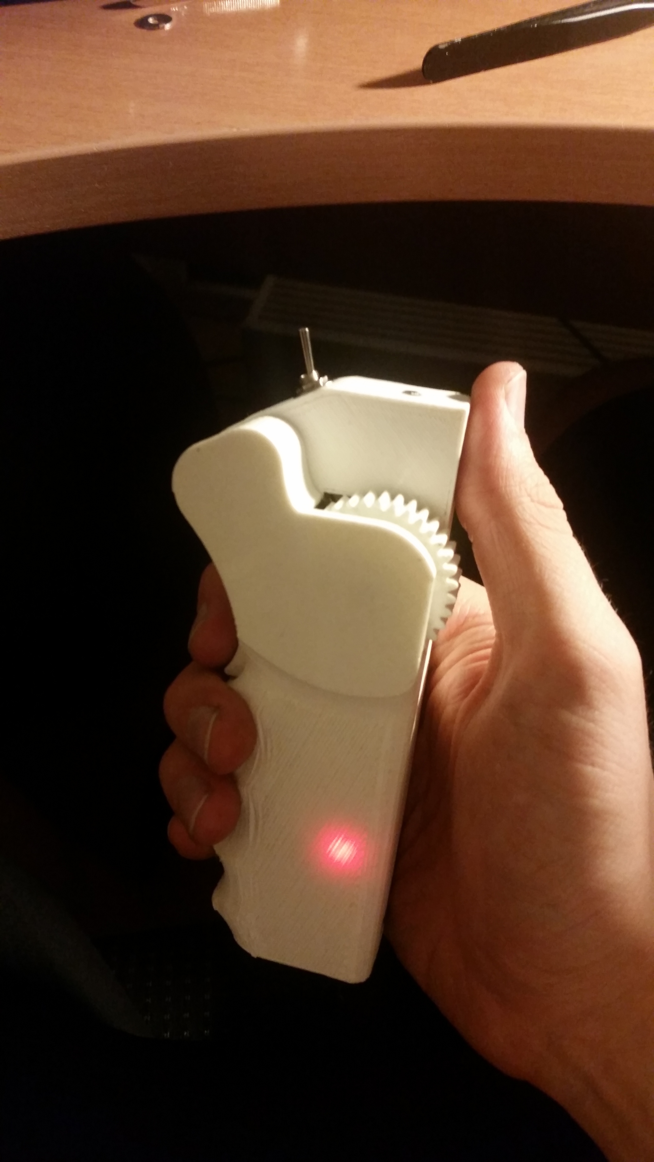
Remote - printed in PLA, quickly thrown together in CAD with a 18650 cell and an arduino nano. NRF24 is the tranceiver here and a potentiometer for input, a safety trigger exists. Oh, more idiot points are earned here by using a gear reduction for the potentiometer (i wanted a smaller travel for the full range) and a spring loaded cam mechanism for returning the thing to center. Yeah…
Battery - DIY 10S4P VTC6, cells and the “technology” supplied by my workplace, so I cant really show much of it or I would get sued  Lets just say it has a shit load of fuses… per cell. And also a lot of copper is involved, that much you can spy in the photos below.
Battery case - designed and printed in PLA, could have been made smaller in hindsight, nothing fancy.
Motor - E-MAX GT5345, when I got this SK3 were out of stock for months. It is size equivalent of a 6374. But to be honest does not impress, rather large air gap between stator and magnets, the magnets look like they were glued inside the bell by a todler, unequal gaps, some are at an angle, ammounts of epoxy vary all over the place. Would not reccomend.
Mount - self “designed”, come on, its just a 5mm stainless steel plate, laser cut, with a diy idler pulley.
Pulleys - HTD 5M steel 16 teeth for the motor and printed in PLA 85 teeth for the wheel.
Trucks - DIY, basically NoSno rip offs, but from steel. Yes, they are heavy. The axle is 25mm diameter. Solid. Shin breaking stuff. “Bushings” are industrial vibration isolators, with sides cut off. Hardness is 55A if memory serves. Let me tell you, cutting them with a knife sucks a lot. WD-40 helps immensly.
Wheels - 225mm diameter (8.8 inches), steel hubs, basically cartwheel stuff. Making mounting holes is nearly impossible without a mill, so I designed and printed a hub for the driven wheel (PLA)
Lets just say it has a shit load of fuses… per cell. And also a lot of copper is involved, that much you can spy in the photos below.
Battery case - designed and printed in PLA, could have been made smaller in hindsight, nothing fancy.
Motor - E-MAX GT5345, when I got this SK3 were out of stock for months. It is size equivalent of a 6374. But to be honest does not impress, rather large air gap between stator and magnets, the magnets look like they were glued inside the bell by a todler, unequal gaps, some are at an angle, ammounts of epoxy vary all over the place. Would not reccomend.
Mount - self “designed”, come on, its just a 5mm stainless steel plate, laser cut, with a diy idler pulley.
Pulleys - HTD 5M steel 16 teeth for the motor and printed in PLA 85 teeth for the wheel.
Trucks - DIY, basically NoSno rip offs, but from steel. Yes, they are heavy. The axle is 25mm diameter. Solid. Shin breaking stuff. “Bushings” are industrial vibration isolators, with sides cut off. Hardness is 55A if memory serves. Let me tell you, cutting them with a knife sucks a lot. WD-40 helps immensly.
Wheels - 225mm diameter (8.8 inches), steel hubs, basically cartwheel stuff. Making mounting holes is nearly impossible without a mill, so I designed and printed a hub for the driven wheel (PLA)
Lets start with the end, so far it has seen about 30-40 km of shitty pavements. Which are also the main reason why I went pneumatic wheels. Urethane just would not cut it in most places. I reached 25 km/h so far, for me, that feels like a lot right now (no boarding experience), but I want more hill climbing ability (is it even possible to get up a lets say 20% hill with a single 6374 motor on enourmous wheels?) and the motor gets rather hot rather fast. But i love riding this anyways.
Single drive, because I am a cheapskate.


The (also DIY) printer that birthed all the components. man, it took some effort to upgrade this thing for reliable 24hour prints, and I still have this annoying wobbling of the Z-axis:


Base plates and motor mount plate- mount (lol) after welding. My first “functional” welds (with a MIG, so I guess I was cheating):


Laser cut mounts (got them for cut free cause Im such a nice fellow) and a freshly hand turned pulley:


How the board looked originally and next to it you can see the original “wheels” and my replacements:

Front axle up close:

Loop key:


Before deciding to print a hub completely I was expreimentally arriving at the most correct shape for the existing hubs by printing some flat profiles. Ended up with a massive new hub anyhow:


NRF-arduino unholy union, still missing the 16V 22uf cap in the first picture:


Battery in the box already. Its a weird construction, my second battery (first one was for a motorcycle  ) We had scrap copper plates, I sodlered them into groups with a nasty 200W iron (each connected by 2 fat copper wires- 6sq mm each), then welded the cells. The pack is a two part construction that was bent into shape after completion, you can almost see the bent copper wires in the middle back:

A nice group shot of most of the remote pieces, battrey and the bms:

Finished remote:
Everything mounted into place (vesc had a little holder printed for it, I know the plastic basically touching the FET’s is not a great idea, but it didnt melt in the first 20 minutes  and now its all gone, the BMS sits there at an angle now:

And last but definitely not least - the sketchiest charging solution you could come up with: an old ATX supply with a DC-DC boost converter from aliexpress. Its quite a cool thing, can set up any charge current and voltage, has CC CV, only thing is, it screams an annoying high pitched sound, but it was 14 euros for a basically universal charger, so I think im fine with it. For now:

Questions? No? Class dismissed
 lucky, no need to wait for a month to get it shipped.

