Tom's DIY Buildlog! (Incomplete) - Updated 11/02/16

Hey guys!

Click here for part 2!

I have always wanted to get an electric skateboard, be it an enertion board, boosted board, evolve, etc. But they are all way out of my price range, so I figured after reading an instructable online, that I could build my own. (with blackjack, and hookers!)

So here goes my attempt!

I live in Adelaide, Australia, so parts arnt that easy for me to get here, but thanks to ebay and Jason from enertion, I have been able to source all of my parts, so far for under $500!

###Planning stage:

There are plenty of options out there for DIY, but they all look pretty shoddy, and generally have pretty shit advice that will probably either blow up your board, or cause yourself to get seriously injured when it fails.

Here, I have planned a DIY electric skateboard which I believe will be stylish, functional and safe to ride.

So, lets get started!

Here is a list of nearly every single part needed:

###Parts:

  • Longboard deck
  • Motor - Hobbyking SK3 5055 280kv
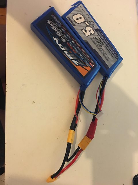
  • Batteries - 2x 3s 5000mAh LiPoā€™s
  • ESC - Hobbyking Aerostar 80A
  • 6mm Aluminum Bar - min 50x120mm
  • Small Pulley - XL15 5mm pitch, 6mm bore
  • Large Pulley - XL40 5mm pitch, 12mm bore
  • Belt - 114XL 57 Teeth
  • Arduino Nano
  • Wireless Wii Nunchuck
  • Solid State Relay module
  • 24V push button switch
  • 4mm bullet connectors
  • 2x Washers - 50mm OD, 27mm ID
  • M4 Nut inserts
  • JST Extension
  • Bearings
  • 83mm Flywheels
  • 3mm Black ABS A4 Sheet
  • 2m 8AWG Cable
  • M6 70mm Bolts, Nylock nuts and washers

This list is not complete, I will be updating it regularly!

Here is a full cost breakdown and links to all items: DIY Skateboard Build of Materials

For the motor mount, I used a design from another build on instructables, that a lot of builders are using

And here is my version I cut using a dremel and a cordless drill!

Anyway, thatā€™s all for the planning stage, now to wait for my shipments!

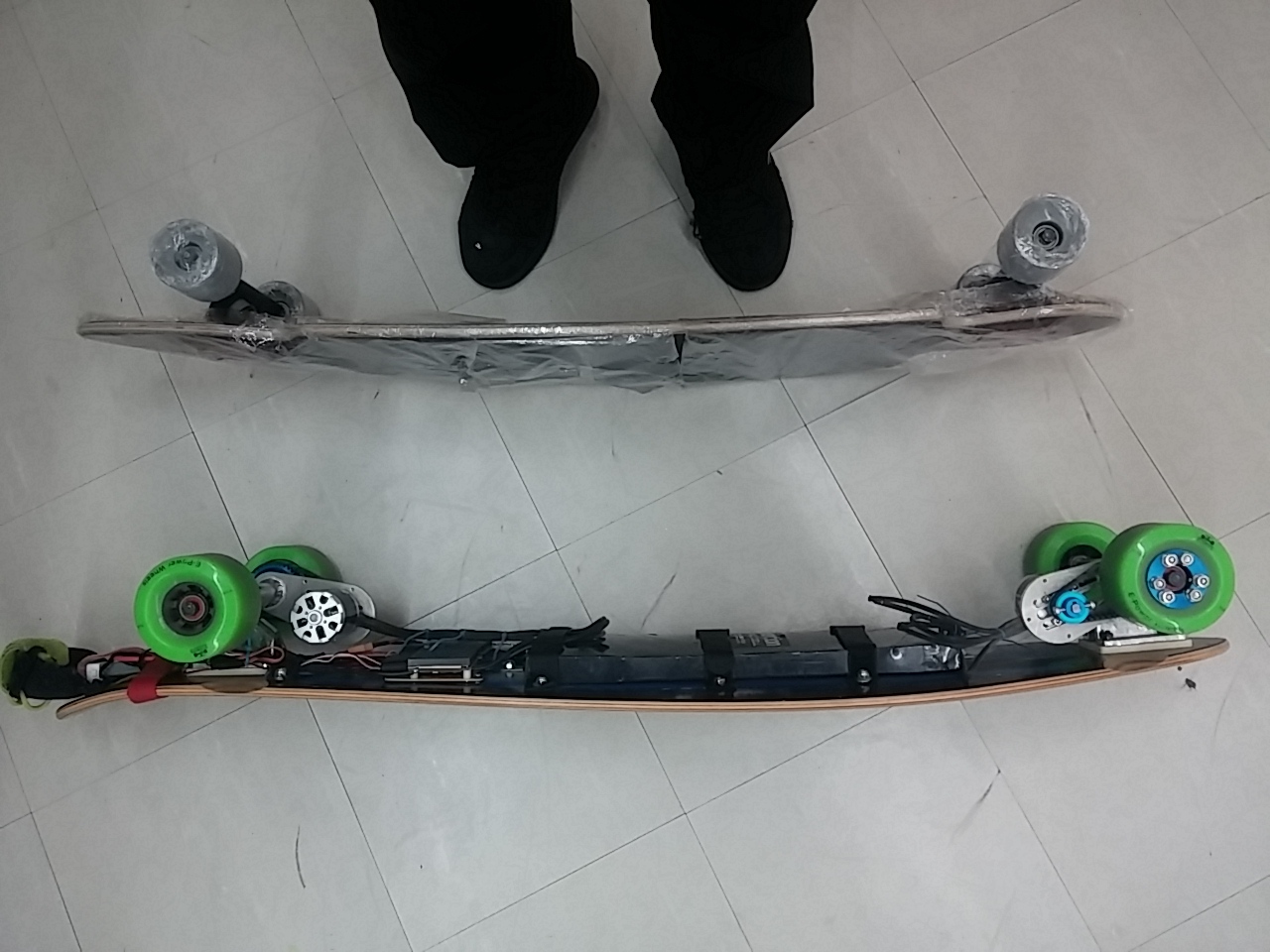
Teaser: Here is the deck I am have had for years, and the new flywheels from Enertion! They look sick!

Cheers!

PS: I know how badly you want too, but please donā€™t tell me, oh why did you use X when Y would have been so much better?, I chose to use the parts I did for various reasons, and I have already purchased everything so it wouldnā€™t change much. Buf feel free to let me know if there is a better option. Just donā€™t nag me!

##To keep up to date, I have a blog here: http://tombrereton.com which will house full versions of all of my updates and other projects!

HEY TOM! welcome!.. nice wheelsā€¦ :slight_smile: Its great to see some Adelaide folk getting in on the eboard action!

If you attempt to use the 24v switch directly to cut off the battery supply to ESC make sure that the switch / relay could handle the spark or the Amps (about 20 - 30 Amps). Means that there are only several rocker switch out there who are able to handle it. Otherwise youā€™ll need electronic switch for cutting off power.

If youā€™re quite heavy, might be wiser to get lower KV motor like 240 / 190 / 149 for single motor as they provide much better torque to pull you up hill / to start from stand still.

I have a 100Amp solid state relay for switching. And I am light so Iā€™m not worried about the motor. Especially as where I live isnā€™t hilly at all :smiley:

Looks like a good build. Not sure about that ESC though. Just wanted to point that out and see what others have to say about the ESC.

Welcome to the forums! Good to see another Aussie on here.

Cheers!

Yeah the ESC was abit of a stuff up, didnā€™t realise it didnā€™t have reverse until after I received it. Iā€™m going to try it out and if it sucks Iā€™ll get a new one :smiley:

1 Like

Thanks!! The bigger wheels feel so much better already even on my normal board :stuck_out_tongue:

Just waiting on my pulleys and belt before I can do a test run!

the XL pulley tooth profile is not very common for eboard, if you have problems with it let me know ill do a deal on some 5mm HTD pulleys & belt! Always happy to help a local customerā€¦

yeah ! Sector 9 . same as mine .

about 43inch . with enertions space cell batt , dual diagonal trucks Diyelectricskateboard . Torqueboards escs . and nunchuck remote . you need to patiently read the topic about nunchuck controllers from ESK8 posts . i had several problems til i hot glued the tiny little 4 wires that are SURE to break from all the vibrations from riding the eboard .
ā€¦ i found out about the ESK8 postā€™s on nunchuckā€™s safety tips AFTER i solve my problems with that tiny 4 wires at the receiver end that connect to the ā€˜wii moteā€™ . i totalled 1 nunchuck which is now useless . now iā€™m using a second spare nunchuck . i still have another nunchuck still in its packaging . check my videos . that other longboard is another 36inch ā€œcamberā€ longboard i was comparing & considering with mine (43inch) for my next single drive eboard . after my experience with sector 9 ā€œcamberā€ type of longboard , i might just change to ā€œrockerā€ type of concave longboard . still ! i would look for 43inch ones

check out my videos .

Yeah it was really the only pulleys I could find on ebay :stuck_out_tongue: If they are shit ill let you know!

I have built a lot of boards with XL pulleys. they work fine, but you may get belt slip going up steep hills with a single drive.

HTD are obviously better, but XL are cheap and easy.

###Update 11/02/16 - Electronics!

####Arduino Setup: For the brain of my skateboard, I am using an arduino nano running a modified version of the wiiciever code found here.

I modified the code to allow me to monitor the voltage of the battery using a few LEDā€™s.

Here is a list of components used:

  • Arduino Nano
  • Perfboard
  • Small buzzer
  • 5 Red LEDā€™s (might get some yellow and green ones)
  • 5 150 Ohm resistors
  • 1x 120K and 1x 27K ohm resistors
  • 1x 4 pin, 1x 3 pin, 1x JST Female headers
  • Wire

Use this diagram to wire up all of the electronics.

Feel free to ask for any clarification on this.

NOTE: I swapped my ESC wires positive and negative cables to make it easier to connect to the arduino. Please either swap the cables or rewire the pins on the arduino!

Your finished board should look like this: Front:

Back: I know my resistors are not 150 Ohm, but that is all I had on hand and they work fine.

Using a usb cable, download my modified code here: https://drive.google.com/folderview?id=0B8fFkWnAIp8qZ1puVUhCUG04OFE&usp=sharing

And using the arduino IDE push this to the nano. Once done the electronics setup is done. ####Power Setup: Here comes the annoying part, soldering together the power cables. Due to them being so thick, you need to have a good soldering iron, and be patient when soldering to avoid cold and weak joints.

Parts list:

  • 2m 8 AWG Cable
  • Solid state relay
  • 24v push button with LED
  • heatshrink - various sizes and colours
  • 2x XT60 Connector sets
  • 2x JST male, 1x JST Female
  • ESC
  • 2x 3s LiPos
  • XT60 Series harness (or DIY)

Follow this diagram to setup the power system:

You should end up with something like this:

I use the jst connectors to make it easier to swap components if needed, and for the pushbutton as it will have to be unplugged when installing into the enclosure. Also, I preinstalled 2 cable grommets for future installation in the enclosures. If you are doing the same, do this before soldering on the connectors.

Regarding the 2 lipoā€™s in series. Use a series connector to connect the packs together, and then use either a series balance connector to connect the balance plugs, or is you have a spare 6s balance plug, rewire that one to work with the 2 batteries. You will have one left over wire you must splice this positive wire with the negative of the other pack. Most series adapters sold will already do this, but I manually connected mine and had to solder them together!

Connect batteries as shown:

And that is the power and electronics done! If you need any clarification on what I have done, feel free to ask in the comments below!

Teaser: I have been painting my trucks and the motor:

Using Self etching primer and flat black spray paint, I got amazing looking results! So far I have sprayed the Motor, trucks, and some nuts and bolts. Waiting on my pulley to arrive before spraying the outer rim of that too!

This truck isnā€™t painted yet as I am waiting for my pulleys to arrive before welding on the motor mount. I may have accidentally already primered it :stuck_out_tongue: For the nuts, I just put some masking tape inside the hole and sprayed the visible bits And the bolts for the pulley:

##To keep up to date, I have a blog here: http://tombrereton.com which will house full versions of all of my updates and other projects!

Yeah I figured Iā€™d atleast try these ones before opting for the more expensive option. Not a huge loss if they do start to fail.

Good work. Clear schematics. I like it. I actually did something very similar to monitor my battery voltage, I used a 128x64p OLED display, for which I wrote some code to display a bar-graph.

Same principle as yours, voltage divider. Iā€™m now planning to get individual voltages from my cells as well, using the balance leads. I havenā€™t mounted my display on my board yet, Iā€™m still figuring out how to best weatherproof it.

Ah thats cool! I just wanted something extremely simple.

Do you have an enclosure? Could you dremel a square out, glue in some clear plastic and then mount the screen behind that? :smiley:

I want to be able to view it from the top of my board. Iā€™ve thought of potting it with clear plastic along the front but I havenā€™t come around to it yet. Soon.

Ah yeah that will be tough! Good luck with it

Quick Tip!

I made the mistake when connecting the 2 3s lipos in series, to just not include the red wire from one of the packs as I saw on a online tutorial.

This caused one of the cells to not be balances, and the charger never would reach full charge due to this.

To rectify the issue, you need to splice the red wire into the negative of the other battery. I will update my post above to show this.

Hopefully this will help anyone who has an out of balance series lipo!

thats incorrect. leaving the red wire off is correct and would no cause cell imbalance. there is something else wrong if that is the case .

Are you sure? If I left the red wire off my LiPo wouldnā€™t balance at all, with that one cell always being a few mV down. After connecting it balanced perfectly.

Look at all pre made balance adapters, they all connect them