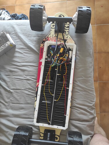
Hey guys, I am new to the scene and a total noob but have some background in electronics and engineering. I just finished my first complete DIY build a few days ago but I am still struggling with amking everything work as it should.
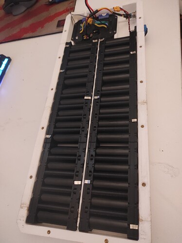
I have a rather simple setup with not to much going on. The battery is a DIY build in a 10s3p config (Sony VTC6 cells). This works perfect and I tested it on my bench multiple times cycling throught the whole capacity.
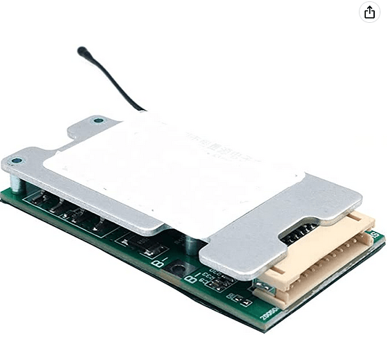
The BMS I used is a cheap 30A 10s BMS module from amazon; a very generic one:
https://www.amazon.com/gp/product/B083QCGBKN
The motors I use are two 600W each Hub Motors with hall sensors; to be precise these 90mm ones:
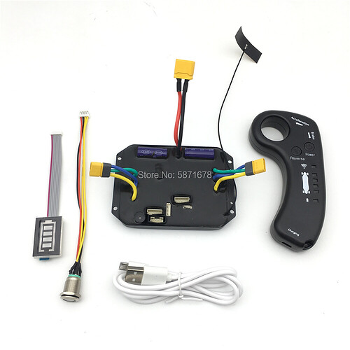
My ESC is a potted one so it is very hard to tell what it is in particular but from the controller and overall layout and appearance I am highly convinced its one of these cheap generic chinese ESCs; the particular one I bought is this one:
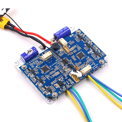
Tho I am very sure its just a potted version of this one (exemplaric);
Now to my problem; While testing and idling everything works well. Well after some adaptations at least… While frist trying to get it to work the motors where just vibrating violently and didnt move at all. I figured out that the order of hall sensors must be inverted or scrambled as this would explain the noise due to wrong commutation. I inverted the pins of the hall connector (from what I suposed to be UVW to WVU). After this the board accelerated with the remote in idle without any problems; so I thought thats great and wanted to ride it. So I step on the board and start driving but after like 800m or something the remote signals me the battery is low even tho it was fully charged on my departure. So I carried it back home, charged the battery and tried again. Same result…
I then figured there is something off with the hall sensors still as the motors where also very very noisy compared to what I am used to from prebuilds ( I have a 140$ single drive toy board that is not as noisy as this). My assumption is that commutation is bad and thus current spikes drain the battery very fast and hard which would also explain why the motors run very hot (barely touchable without burning) after just like 800m driving on a flat street with like 10km/h. I tried disconnecting the hall sensors compeltly and using it in sensroless mode but noticed the voltage on the battery draining very very fast nevertheless just like before (I guess as the phase current is way higher than it should be) and the motors heating up rapidly.
The strange thing is, the board just died after a short distance again (with no hall sensors) but on returning and plugging in th ebattery to charge it only takes like 15min until its full again and I can turn it on and “use” it again to its full capacity, so my guess here is the BMS just triggering the overcurrent protection at a certain point as I can not even turn on the controller afterwards anymore. This short charge “resets” this trigger in the BMS and the ESC turns back on and tells the battery voltage on the remote again.
Do you have any idea what is going on and how I can troubleshoot my build? I am pretty sure the phases are inverted or in a wrong order but as the ESC is potted I can not read any pin names etc neither from the motor phases nor the hall effect sensors and by matching them by colors (green, yellow, blue) it didnt work (this was the first thing I did where it just started vibrating violently).
Some pics:
