You are using a nunchuk so you will need to use the canbus to control the second VESC. I have not tried splitting the leads on a wii dongle yet but it may work. Better to use the canbus though.
If you where using a conventional FHSS transmitter you could split the receiver output leads and control both VESC through the ppm input. Be sure to only have the red wire coming from one vesc if you do this.
This is my setup. Actually I just want to try and see what happen if I didnt do the setting as previous comment. But yeah, I’ve encountered some problem such as one of the motor suddenly stuck or pause. Maybe because I didnt put any ID or set the slave or master.
This is my dual setup picture and @chaka , that means I need to cut which wire? because im using a bit different color for the wire and got confused. Im also using 2.4ghz mini controller.
When @onloop says that we need to click the send status over CAN for the slave. Just to make it clear, u need to tick or no tick it? haha sorry for my bad English.
[quote=“chaka, post:43, topic:142”]
Leave it on your master vesc,
[/quote] Unless you have a ubec/sbec around. The center wire powers the receiver and the power should come from only one source.
What @chaka is saying is that you cut the red wire coming from one of the VESC and leave the other connected. You see, the red wire is what feeds power to the receiver. You only need the power to come from one of the VESC, it doesn’t matter which VESC the power comes from but the receiver should only receive power from one of the VESCs.
If you’re using CAN bus in a master/slave configuration, the receiver should only be connected to the master.
First you need to make sure both VESC’s are working properly by connecting each one to the BLDC tool and using the arrow keys on your keyboard to run the motor. Once you’re sure they are both OK, you can set up CAN bus:
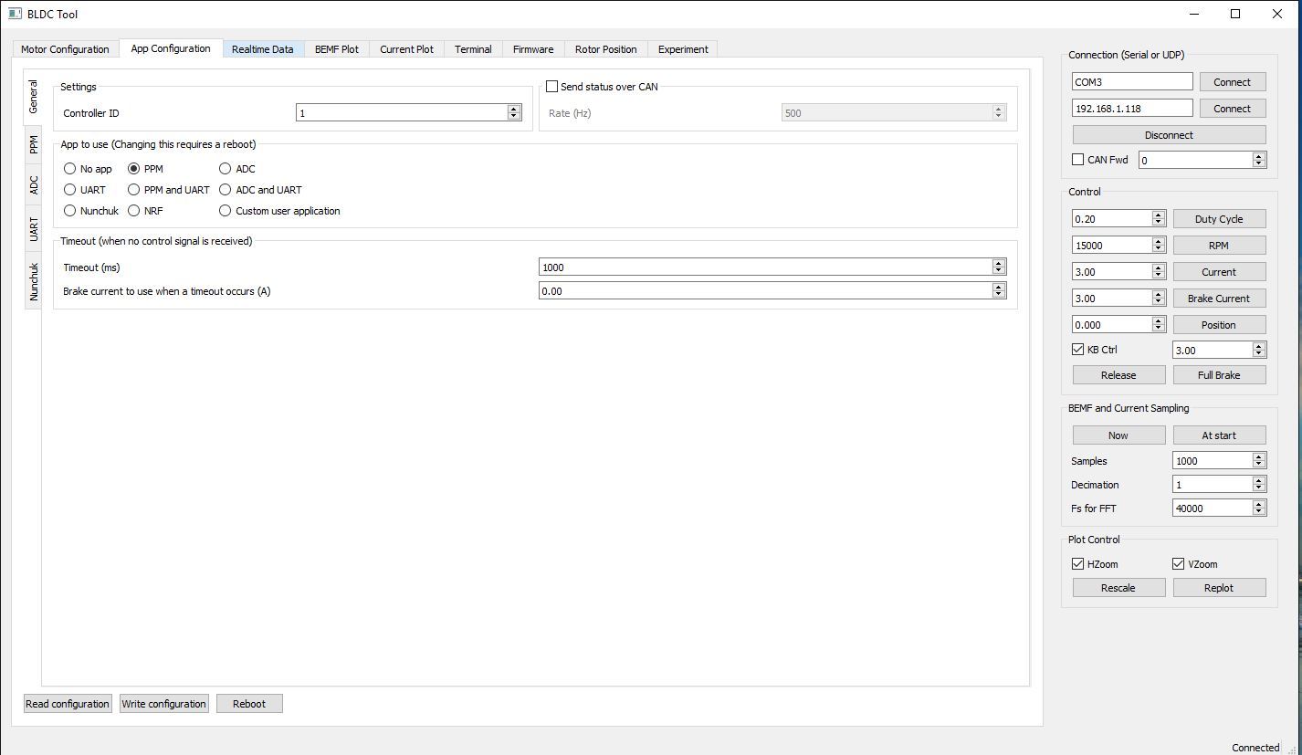
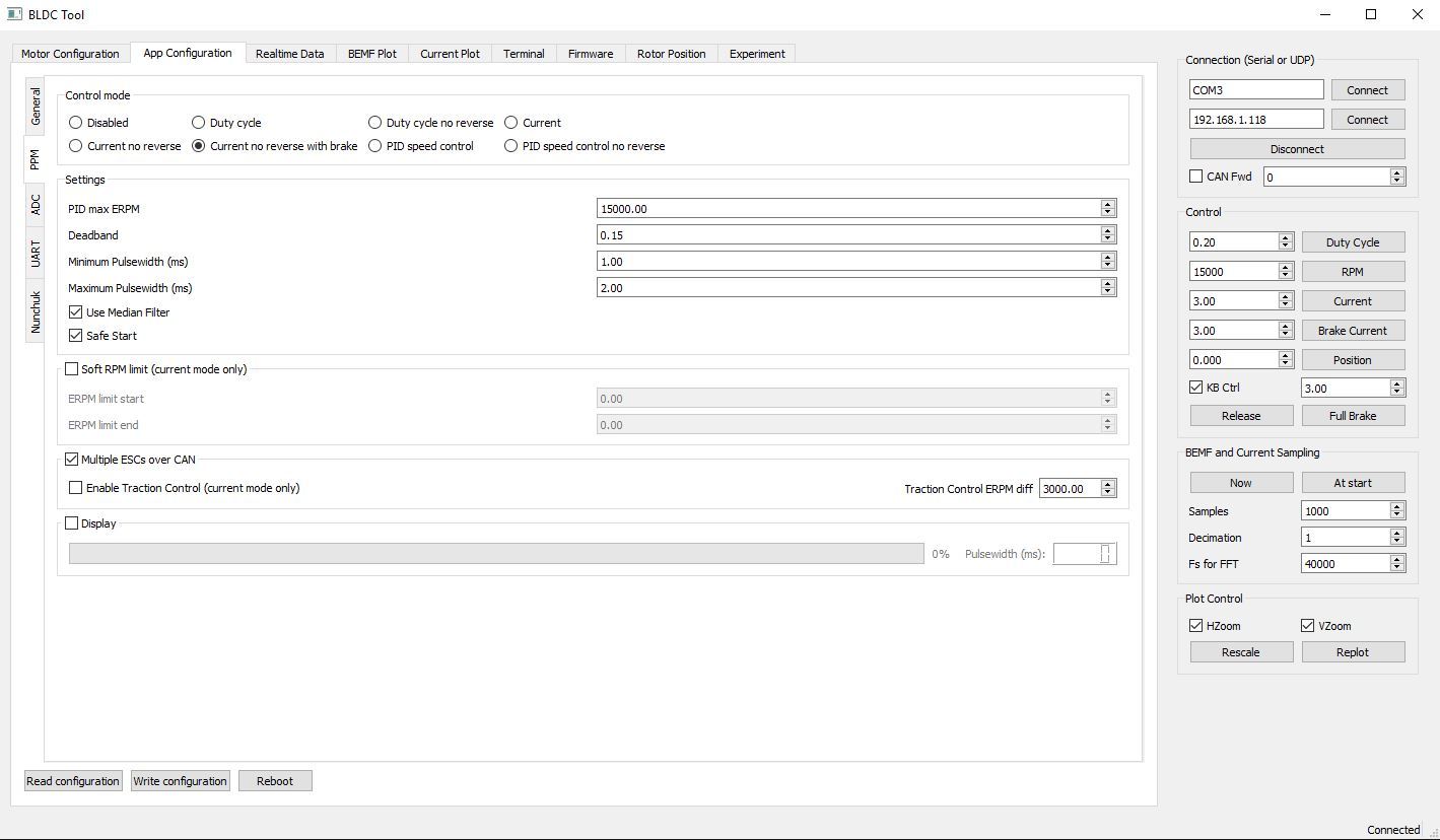
Connect master to BLDC, give the master ID 0, configure the PPM settings (write conf) for your receiver and test to see if your motor runs. Don’t connect the slave to the master yet. Put your transmitter aside.
Connect the slave to BLDC and give it ID 1 and tick " send status over CAN" - (write conf).
Disconnect the slave from BLDC.
Connect both VESC’s with the CAN bus cable.
Cycle the power on both VESC’s off an on.
Reconnect the master to BLDC and tick “CAN Fwd” on the upper right of your screen, enter ID 1 To receive data from slave.
Goto the realtime data tab, tick “activate sampling” and verify there’s data coming back from the slave. You should see the graphs move. If they don’t, there’s no communication.
Now take your transmitter and pull the trigger to see if both motors spin.
Correct, If you’re using CANbus, the receiver is connected to the master only.
The app for the receiver is configured only in the master.
The master takes care of the control of the slave.
Thanks, that means WITH the CANbus setup, the one connected to the receiver becomes the master one?
So is that possible to do a different way on dual Vesc which like old esc setup that “without CANbus then connected both receiver side with the ‘Y’ bridge then take one side’s middle wire out”
If you use a Y connection You won’t have traction control but I’m pretty sure you wont miss it.
You won’t be able to get realtime data from both vescs over the same usb connection either, you’ll need to plug into each vesc separately to look at realtime data.
It will make config straightforward though, you can set both vescs up identically.
Very helpful info mate. Thank god I’ve asked those question. Didn’t even know that before. Then now I know what setup I’m going to run in future. Cheers!


 Unless you have a ubec/sbec around. The center wire powers the receiver and the power should come from only one source.