(This post is copy of my last message on my previous post, I thought that it would be better to have one issue per topic in order to find it later)
Hi guys ! 
new update, I’ve almost finished my vesc. Today I soldered the caps and tried the board on +15v lab power supply. However it locked itself (due to high amp consumption) and I saw some smoke coming from the board… 
When I power it up with 5v, everything is ok. But if I increase the voltage the current consumption raise up immediatly, like if it was shorted.
The 3v3 regulator works fine but it seems that the 5v line if shorted with the Vbattery.
I checked the circuit on kicad and I saw that the mosfet driver was driving the 5v. Knowing that I did soldered D5 in the wrong way the first time and for some time the board has consumed 2 amps, do you think the mosfet driver is dead ?
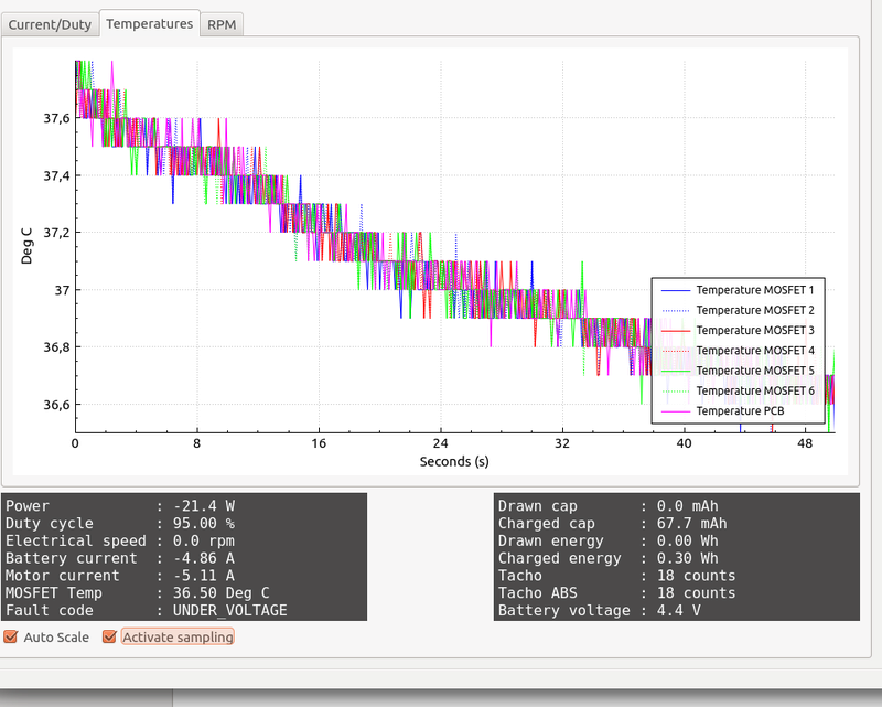
Here some data from bldc tool, strange values (negative power ??  ). Also the micro and MOSFET get quite hot…
If you need more info just let me know
Thanks…
You may have better luck on the vedder.se forum. Alot of those guys build their own
In the mosfet driver is a 5V powersupply. You might have killed that by having the diode reversed.
Looking at the pictures that you posted, I highly recommend to go over the whole board with a microscope and make sure that no shorts exist, especially on the DRV and STM.
Besides that its worth to check the schematics and go over the full 5V net to see if you got a short anywhere there.
About the negative power, that suggests your motor is being spun by an external force. Aka regenerative braking. I assume that is not the case. In the schematics you will find a bunch of voltage dividers. One is for the main power in and it tells us in the picture above that you’re supplying the board with 4.4V. If you give it more or less have a look at your solder joints at these components. Have a look at the other ones to and make sure you got good solder joints there too.
Then check the shunts for bad solder jobs. I mention that last as your soldering looks pretty good everywhere else and I assume you should have no problem to solder the shunts properly.
Thanks you both for tour replies ! I’ll verify all of that asap. Just à precision, all of this has been tested without any motor. I haven’t connected the motor yet…