I have 2 VESCs hw v4.10. One connects to bldc tool, one does not. I get the blue light on the vesc, but nothing else. It is not recognized by the os.
I have 3 different pcs and 6 usb cables.
Here is what I get:
Connected to win 10, 8, 7, xp - not in device manager. No new device at all.
Connected to Linux (ubuntu, centos) - dmesg results: no vesc, no unknown device.
Connected to working vesc via canbus - bldc tool: set CAN Fwd get message that cannot connect
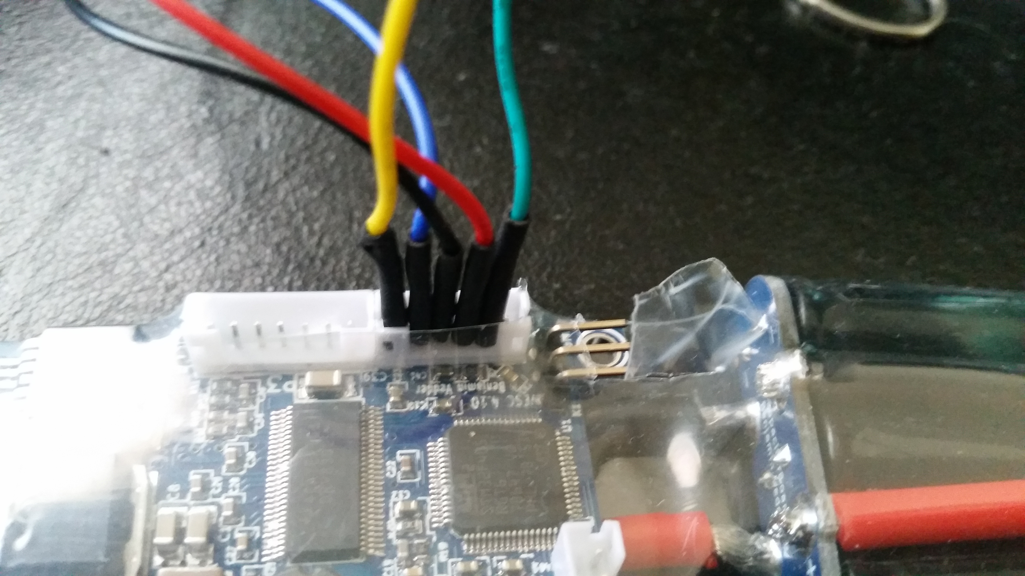
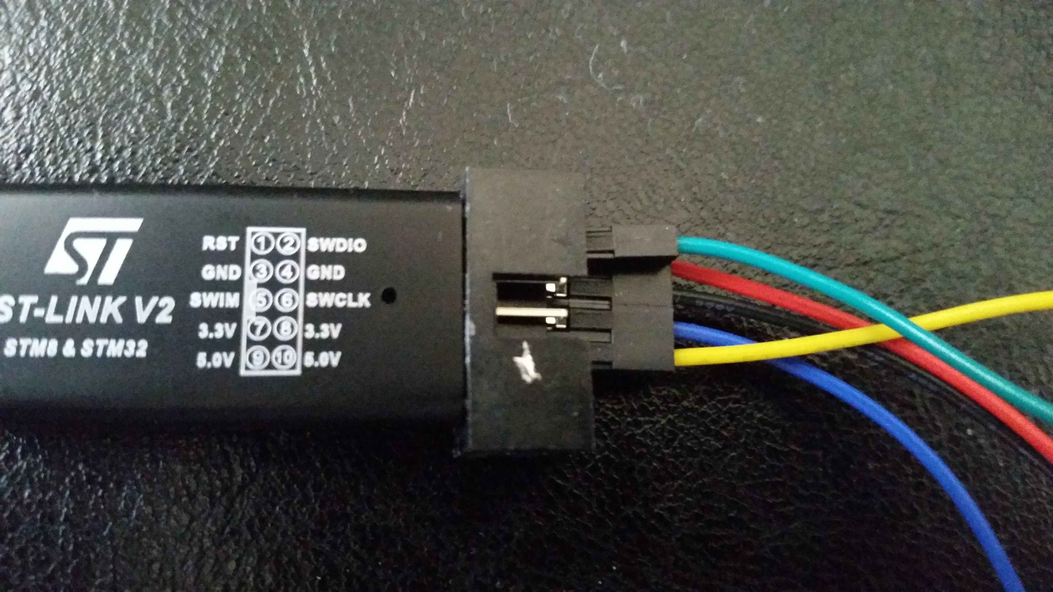
Connected to 2 different stlink V2 - make upload: init failed.
All of these techniques work on the other vesc(except canbus of course) , the one that works.
I have also had stlink wiring checked by someone at vedder’s site and it works on the other vesc.
Yes. I have 2 different stlink v2. I can’t get the make upload to work on the bad vesc. I can get each stlink to connect to os properly. But when I try make upload, I get:
Error: open failed in procedure ‘transport’
** OpenOCD init Failed **
shutdown command invoked.
My apologies, I don’t know where my mind was neglecting you tried to program them with a debugger :(.
Well, in this case (3.3 present and reset @ 3.3):
The STM needs only power to be programmed -> check for shorts and opens in the program wires and if STM is placed with correct orientation ( happend to me, don’t laugh). Can you maybe post a few pictures?
If your wires are really 6" long I am supprised that you managed to program the other ones( did you program the others?). I have bad experience with long wires ( unless you lowered the swd clock speed ).
All other stuff sounds and looks like it should work. Where are you situated? Your name sounds France?