I’ve been developing a controller for my board. From my experimentation it seems the VESC cannot actually properly decode a PPM signal. The port labeled PPM instead seems to take a PWM signal, and my results show that the PWM is the only mode that gives the vesc input calibration proper values. I’ve verified my signal quality by controlling other electronics. Is the VESC documentation just wrong?
For reference, the very popular GT2B generates a PWM signal.
Not sure why there’s an ellipses in your reply. My findings are the same, so my question is why the label says PPM and everyone refers to it as such in all documentation
It looks like it is measuring on-time, which means yeah, probably better to describe as pwm than ppm. Might be a legacy naming convention from the rc world, might be a language translation thing. For most end-users, we don’t care because it’s obviously different than UART
Thanks for looking into it. By definition that’s PWM, kinda mad i wasted a shit load of time debugging my PPM generator because everyone mislabeled it. I know it might not matter to non technical people. But as a developer, and a user of a multi-hundred dollar product i kinda expect the product to correctly document it’s input signal (PPM and PWM are extremely different)
Hey, so i’m super new here (First post, woot woot), and am about to finish my first board. Coming from the drone hobby, i too found it rather strange that its consistently referred to as PPM when its in fact PWM. Would it be possible for us as a community to attempt to label it correctly? Idk too much about github, but could this be a pull request or something? It just seems to me that moving forward, we should refer to certain protocols by their actual names, as opposed to us all just knowing this as some unwritten rule. Definitely could save a lot of headache for some beginners
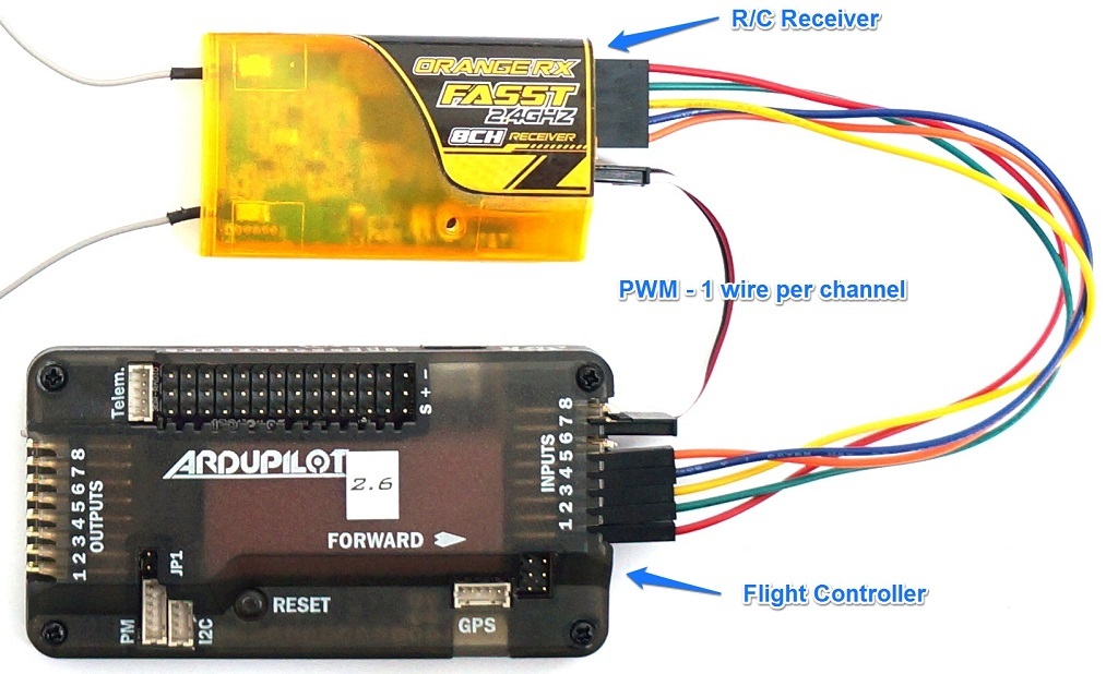
PWM has been around for a long time in the radio control hobby and is the protocol that your ESC’s and servos talk to each other on. The analogue signal takes the form of a pulse, and the length of the pulse represents a specific value, with 1000 being minimum, and 2000 being the maximum value.
Each channel has its own single wire, so if you have an 8 channel receiver you will need to connect 8 wires to read the inputs into your flight controller.
Almost every receiver you can buy will have the PWM output as it is very popular and generally supported by all flight controllers so its a good safe option, however the fact that you need to connect a wire per channel can get abit annoying and possibly lead to mistakes if you get the numbering incorrect.
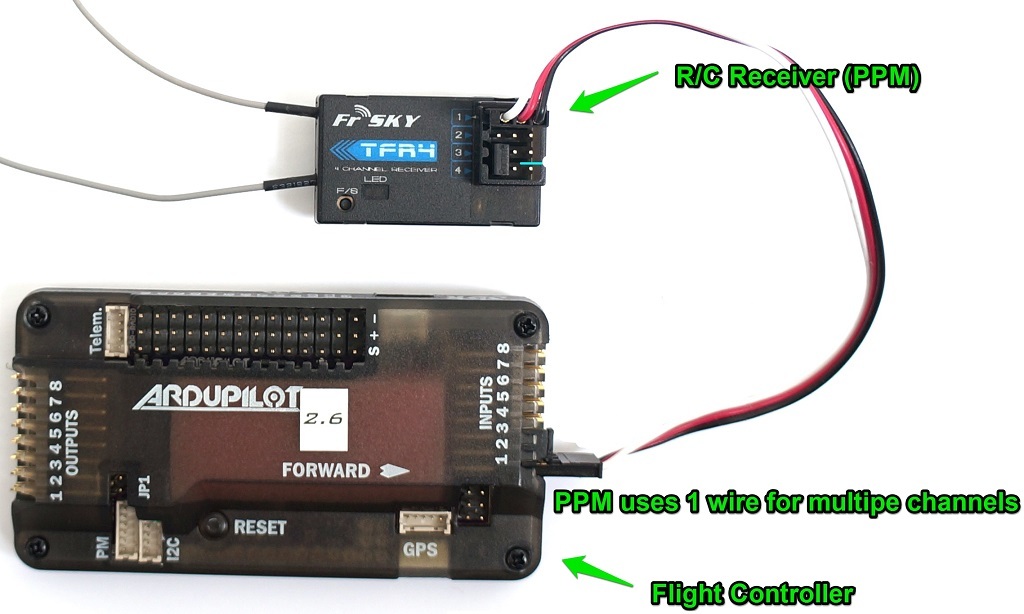
PPM - Pulse Position Modulation
PPM is also an analogue signal, but instead of using a separate wire for each channel, PPM stacks each signal one after another to send them all along the same wire. This makes wiring your R/C Receiver to your autopilot much easier! Other variations of PPM include CPPM, and PPMsum which are slight variations introduced by specific manufacturers.
Yes, I am aware of the difference between PWM and PPM, as is the original poster; and, like the original poster, i question why documentation and venders refer to vesc rc systems as ppm when theyre in fact pwm. And from what i can tell, vesc tool also refers to pwm as ppm. Is it possible im missing something here, that vesc can deciepher between PPM and PWM on the same input line? I havent done any testing myself, but as original poster states, he had no luck with a ppm generator, which is a device that generally takes about 8 pwms (or SBUS, or someother protocol) and converts to single ppm signal. For example, the PXFmini for ardupilot only accepts ppm, so a ppm generator is required, which can convert the SBUS or PWM output of a reciever into single wire PPM (i know SBUS is single wire, but its a different protocol than PPM). My question, which i feel is the same as original poster, if the VESC is known to accept PWM signal, as opposed to PPM, why does the documentation/vendors refer to it as such? And my personal follow up, shoudnt we attempt to correct this?
I am currently trying to control a BLDC motor with VESc 4.12 and (raspberry pi 4) by giving PWM signals through python code with the help of the 3 PWM pins coming out of it but the motor is not running at all. Can anyone suggest me a way other than with oscilloscope to see if VESC is receiving the PWM signals or not or, I think the main thing would be to set the appropriate PWM frequency for the motor to run and I am not sure what it is. I am running out of time, any help would be greatly appreciated