So i was trying to configure my vesc today but it wont power on. I checked the battery and it is at full charge so that shouldnt be the problem. I never had any sparks or shortage while connecting wires or batteries to the vesc. It just got out of the box and on the diyelectricsite they say they check it before shipping so it should work right?!
I don`t have that much experience with electronics so help would be appreciated. I tried to look this problem up on the forum but no-one had the same problem as i do for as far as i could see.
The red wire coming out of your battery goes through your loopkey and than in the black wire of your vesc. The black wire out of the battery goes into the red wire of the vesc. You mixed the polarity
It’s lined up right now. If your vesc like this not powering on now you probably fried your vesc with the last mistake.
Not sure if this vesc has a protection circuit against wrong polarity.
One thing you can try.
Disconnect your loop key circuit from both sides (battery and vesc). Then take a Multimeter if you have one and check the resistance from the xt 90 plugs. Black wire from right to left than red from right to left(with plugged in key) if the resistance shows open end than it means the wires or the plug somewhere faulty. In this case you need to check your solder joints or replace the plugs.
Mate that is so easily done if you don’t follow the rules. The positive wire (red) is always on the square side and the negative (black) is on the rounded side of an XT connector and if you always use the same colour wire throughout your build, red for positive and black for negative you can not go wrong.
On a genuine xt connector + and - is actually embossed on the casing too
Sorry to say it but if there are no lights on your vesc then it is very probably toast and the only consolation is I bet you never do it again.
Thanks for the replies guys. I will pay more attention next time and redo the colour of the lines. I was looking up which multimeter i should buy but the problem is that my battery is 4S 14.8v 10.000mah 10C continuous and 24C peak. Does that mean I need to get a 10x10=100A multimeter or even a 10x24= 240A multimeter!? Or are there other devices that you guys recommend with my setup. Doing 12S made out of the 4S so 44.4V and 45A so i dont overload the vesc.
Just get a hobby multimeter. If you want something good get a Fluke.
You don’t measure under load, so no need that it needs to handle that current. It’s just to check the voltage, polarity or resistance.
PS: here some guys like @Martinsp who repair vescs. Maybe they can help you and will be more cheap than to buy a new one
Hey guys quick update, just bought a multi-meter the one andy recommended. Looked through some forums and managed to repair my vesc . There was some built in reverse polarity protection for the noobs like me hahah. Just tested everything and everything works great. Now planning on making an enclosure and connecting my bluetooth module.


 . There was some built in reverse polarity protection for the noobs like me hahah. Just tested everything and everything works great. Now planning on making an enclosure and connecting my bluetooth module.
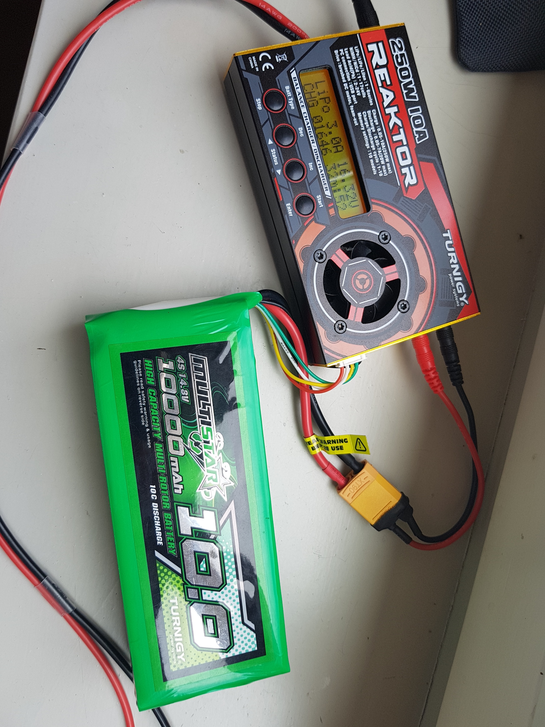