
so a mosfet switch? that’s what the vedder is

It just seems overcomplicated and overpriced then?
It’s not complicated, it’s 3 mosfets in series because you will have trouble finding a single switch able to handle the current and voltage. Someone explain to me what r2 and c1 are for though
All my questions have been answered, thank you. 
Wait, so a “inrush limiter” is not a inrush limiter but rather just a mosfet switch? ?
I think the resistor and cap might be there for inrush limiting but you’d have to ask someone better at EE, I’m just a little programmer
It’s not and it’s not.
you have multiple mosfets in parallel to be able to use high currents and some additional parts to allow a range of voltages and safety features to keep the mosfets healthy.
The switch is like 30 bucks with the most expensive parts being the mosfets and the PCB. a mosfet like this is a couple bucks each so that adds up.
You can make the switch out of breadboard if you want to save a couple bucks.
Thanks you for clearing things up for me
The Zener diode injects a forward voltage of 12V, so the difference between the Gate and Source voltage is independent of the battery voltage
R2 and C1 in combination are the so-called “current inrush limiters”
-
R2 limits the current to C1
-
C1 is a capacitor and therefore it takes a finite time to charge and discharge. When first activating the switch, C1 slowly “fills up” until the Drain voltage reaches is high enough to open the mosfet. If you have a voltage meter installed on your board, you’ll notice it takes a second or two to reach full pack voltage (i.e., not instantaneously)
This is what prevents the spark and activates the circuit… or so I understand it. But I’m a mechanical/aerospace guy, not an electrical engineer ![]()
Very good explanation, but is the current limiting necessary?
Will using only the mosfet wear it out?
Yes. The purpose of this circuit is to (1) switch on/off the high current lines, and (2) limit the inrush of current to the capacitors on the ESC to suppress the spark. Without the current inrush limiter, you have just made an electronic switch. And C1 & R1 are the cheapest components on the board. You’re talking less than a dollar. It doesn’t limit the current of your system - just slows the influx of current on initial contact.
0…10…20…30…40V, instead of 0…40V [spark!]
Thanks for the dummy explanation XD
I just didnt think a mosfet could make a spark, but hearing it’s that cheap, i’ll just include it ![]() thanks a lot for your help.
thanks a lot for your help.
I’ve been using this on my 12s setup for about 2 months, and I used for 4 months on an 8s setup before that. Never had any problems, and it cost like $5 from Lowe’s. All I did was solder it into the wire between my batteries and my VESC.

I would love to know the make & model of that switch. I’ve seen single throw switches that claim to handle that many amps, but they are huge.
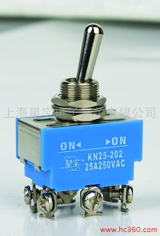
Here’s a picture of the packaging. Like I said, I bought it at Lowe’s. It’s rated for 20A at 125 volts, and since the determining factor in whether or not the switch is burns out is determined by the power dissipated in the wiring of the switch (I think), dividing 125 volts by the 44 volts that 12s runs gives 2.84, so the switch can handle 2.84*20 amps at 44 volts, which is about 55 amps, and like I said, it has yet to fail me after almost 9 months.

very cool, Ill have to check into that.
That is not how that works the only reason the switch did not get destroyed by now is because 20A is fairly high and you have probably been cruising at a lower current most of the time. You still have a spark when connecting so that switch will wear out at some point.